Light source apparatus with modulation function and its driving method

a light source and function technology, applied in the field of visible, middle infrared or infrared light sources, can solve the problems of inability to implement laser oscillation over the entire wavelength domain, inability to implement on/off modulation function in light source, and inability to achieve the effect of increasing sensitivity

Active Publication Date: 2010-03-04
NIPPON TELEGRAPH & TELEPHONE CORP +1
View PDF6 Cites 14 Cited by
  • Summary
  • Abstract
  • Description
  • Claims
  • Application Information

AI Technical Summary

Benefits of technology

[0034]According to the present invention, the light source apparatus with modulation function having practical light intensity can be fabricated. It can increase

Problems solved by technology

Although laser technology has made remarkable progress at present, laser oscillation is not implemented over the entire wavelength domain.
Accordingly, wavelength conversion technology utilizing nonlinear optical effect is an important technology to obtain coherent light in a wavelength range in which the laser oscillation is not easy.
Thus, the ON/OFF modulation function has not yet been implemented in the light source that generates the difference frequency or sum frequency by using the optical waveguide composed of a nonlinear optical material and two semiconductor laser light sources.
In the case where such discontinuities are present, it is very difficult to carry out the light output stab

Method used


Image

  • Light source apparatus with modulation function and its driving method
  • Light source apparatus with modulation function and its driving method
  • Light source apparatus with modulation function and its driving method

Examples


embodiment 1

[0058]In the example 1, a wavelength conversion device module using LiNbO3 as the nonlinear optical material is fabricated, and a light source apparatus with modulation function is fabricated which outputs wavelength converted light by using as the pumping source a 1.064 μm semiconductor laser with an FBG for stabilizing the wavelength and a 1.32 μm-band wavelength variable laser.

[0059]FIG. 4 shows a fabrication process of the wavelength conversion device. In the example 1, the wavelength conversion device is fabricated by using a ridge waveguide structure using a direct junction substrate. More specifically, the wavelength conversion device is fabricated by joining a Z-cut, Zn-doped LiNbO3 substrate 51 that has a periodic polarization inversion structure formed in advance and that serves as a first substrate, and a Z-cut, Mg-doped LiNbO3 substrate 52 serving as a second substrate. Both the substrates are a 3 inch wafer whose both sides are optically polished, and are 300 μm thick. ...

embodiment 2

[0070]The example 2 employs the light source apparatus with modulation function with the same configuration as that of the example 1. Here, the driving conditions of the pulse driving power supply 77 are limited.

[0071]FIG. 8B illustrates the current-light output characteristics at that time. In the example 2, as in the example 1, the output light emitted from the 1.064 μm semiconductor laser 71, which has the FBG 73 stabilize the wavelength, has the smooth differential efficiency characteristics except for the positions at which the light output kinks take place.

[0072]First, the temperature control of the 1.064 μm-band semiconductor laser 71 is carried out so that the initial kink current value in the current-light output characteristics is set at nearly maximum. In this case, the lower limit of the current modulation range is set at a value equal to or less than the threshold value, and the upper limit is set at a current value slightly lower than the current value that will provid...

embodiment 3

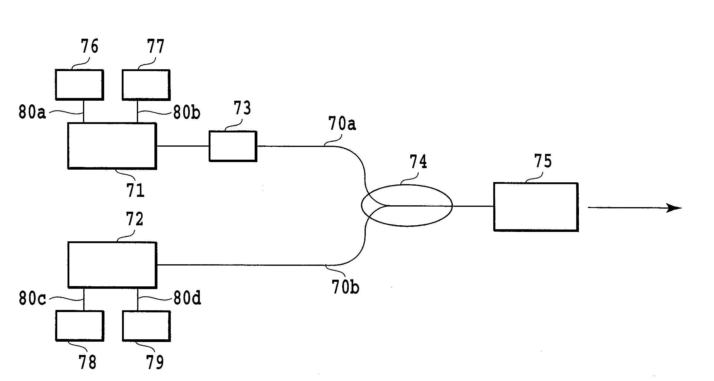
[0073]FIG. 9 shows a light source apparatus with modulation function having an isolator 81 just behind the FBG 73. The input side fiber of the wavelength conversion device module 75 is fusion spliced to the output fiber of the 1.06 / 1.32 μm WDM coupler 74. Second, the 1.06 μm input fiber 70a of the WDM coupler 74 is fusion spliced to the isolator 81. In addition, the isolator 81 is fusion spliced to the FBG 73, and the FBG 73 is fusion spliced to the 1.064 μm-band semiconductor laser 71. Here, the FBG 73 is placed outside the 1.064 μm-band semiconductor laser 71. Furthermore, the 1.32 μm input fiber 70b of the WDM coupler 74 is fusion spliced to the output fiber of the 1.32 μm DFB laser 72. The 1.064 μm-band semiconductor laser 71 is connected to the temperature control unit 76 and to the pulse driving power supply 77 via the connecting lines 80a and 80b. The 1.32 μm-band DFB laser 72 is connected to the temperature control unit 78 and to the DC driving power supply 79 via the connec...


PUM


Abstract

A light source apparatus with modulation function has a wavelength conversion module (75) composed of a nonlinear optical material with a structure having a nonlinear constant modulated periodically. It outputs a difference frequency or sum frequency produced by multiplexing pumping light from semiconductor laser light sources (71) and (72) with different wavelengths through a WDM coupler (74) and by launching the multiplexed light into the optical waveguide. The semiconductor laser light source (72) includes a diffraction grating. The semiconductor laser light source (71) includes a section for modulating output light emitted from its semiconductor laser, and is connected to an external FBG (73) which has a reflection band narrower than a resonance wavelength spacing determined by the device length of the semiconductor laser. The FBG (73) is supplied with the modulated output.

Description

TECHNICAL FIELD[0001]The present invention relates to a visible, middle infrared or infrared light source using second-harmonic generation, difference-frequency generation or sum-frequency generation effect produced in a nonlinear optical medium, and more particularly to a light source apparatus with modulation function capable of varying the intensity of light generated.BACKGROUND ART[0002]Although laser technology has made remarkable progress at present, laser oscillation is not implemented over the entire wavelength domain. Accordingly, wavelength conversion technology utilizing nonlinear optical effect is an important technology to obtain coherent light in a wavelength range in which the laser oscillation is not easy.[0003]Among nonlinear optical effect, the application of wavelength conversion devices is expected which generate a second harmonic, sum frequency or difference frequency by pseudo-phase matching by making use of the second order nonlinear optical effect (see Patent...

Claims


Application Information

Patent Timeline
IPC IPC(8): G02F1/025G02F1/365G02F1/377
CPCG01J1/32G01J3/108G01J3/433G02B2006/12097H01S5/4087H01S5/005H01S5/0078H01S5/0092H01S5/4012G02F1/3534
Inventor MAGARI, KATSUAKIYANAGAWA, TSUTOMUNISHIDA, YOSHIKIMAWATARI, HIROYASUTADANAGA, OSAMUASOBE, MASAKISUZUKI, HIROYUKIMIYAZAWA, HIROSHIYUMOTO, JUNJI
Owner NIPPON TELEGRAPH & TELEPHONE CORP
Why Eureka
Try Eureka