
High speed SRAM

a high-speed, sram technology, applied in the field of integrated circuits, can solve the problems of increasing the chip area, increasing the driving current and rc delay time, and affecting the operation of read and write operations, so as to reduce the power consumption, eliminate the penetration current, and reduce the turn-off current

Inactive Publication Date: 2010-03-04
FRONTEON
View PDF13 Cites 54 Cited by
  • Summary
  • Abstract
  • Description
  • Claims
  • Application Information

AI Technical Summary

Benefits of technology

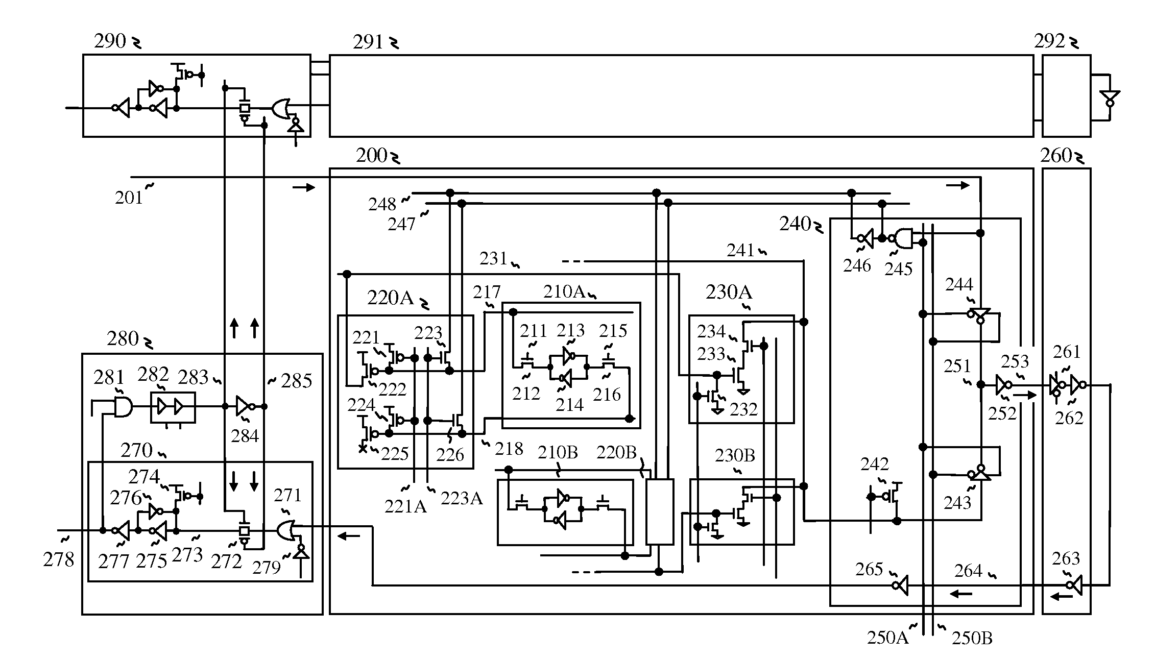
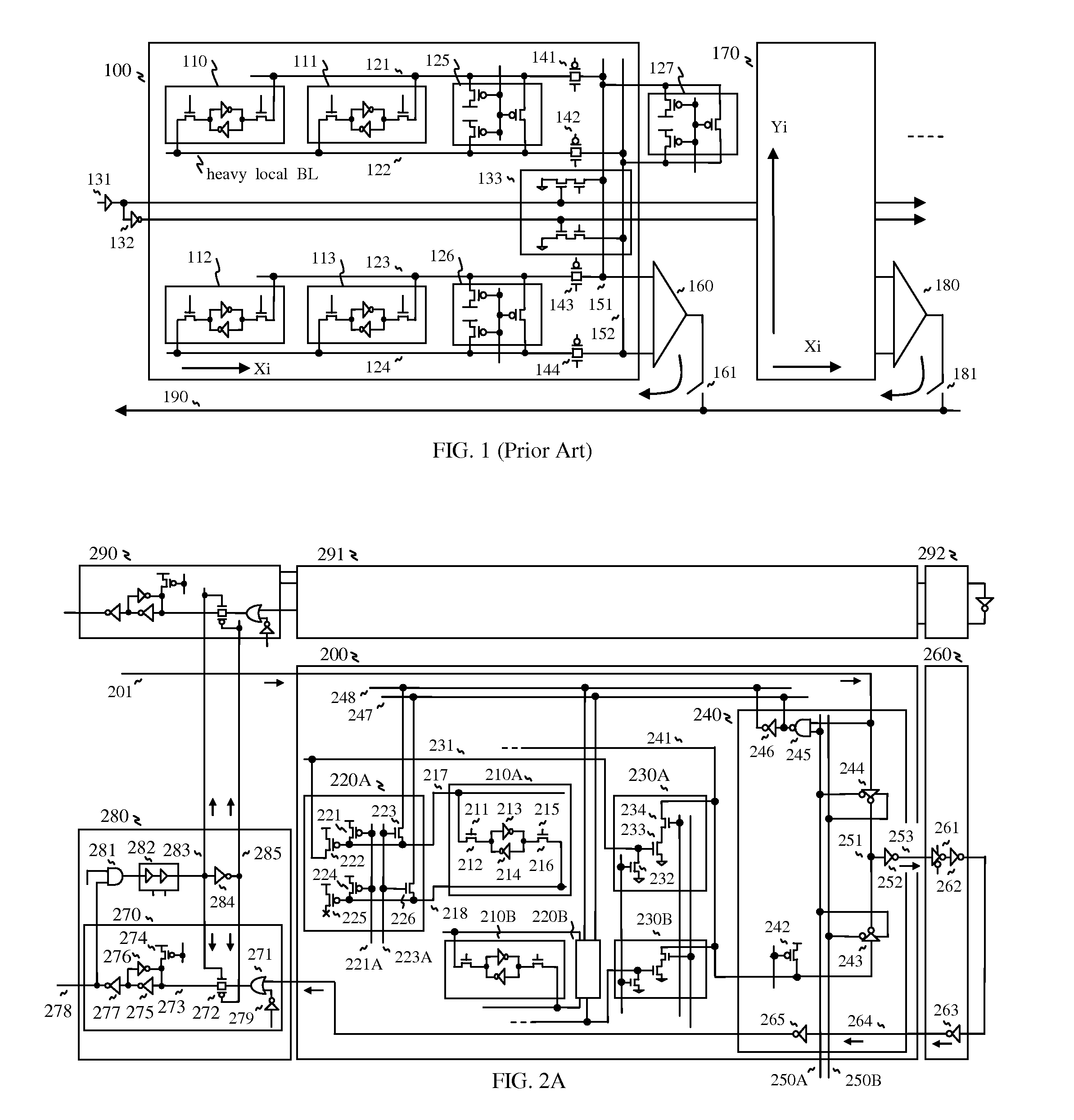
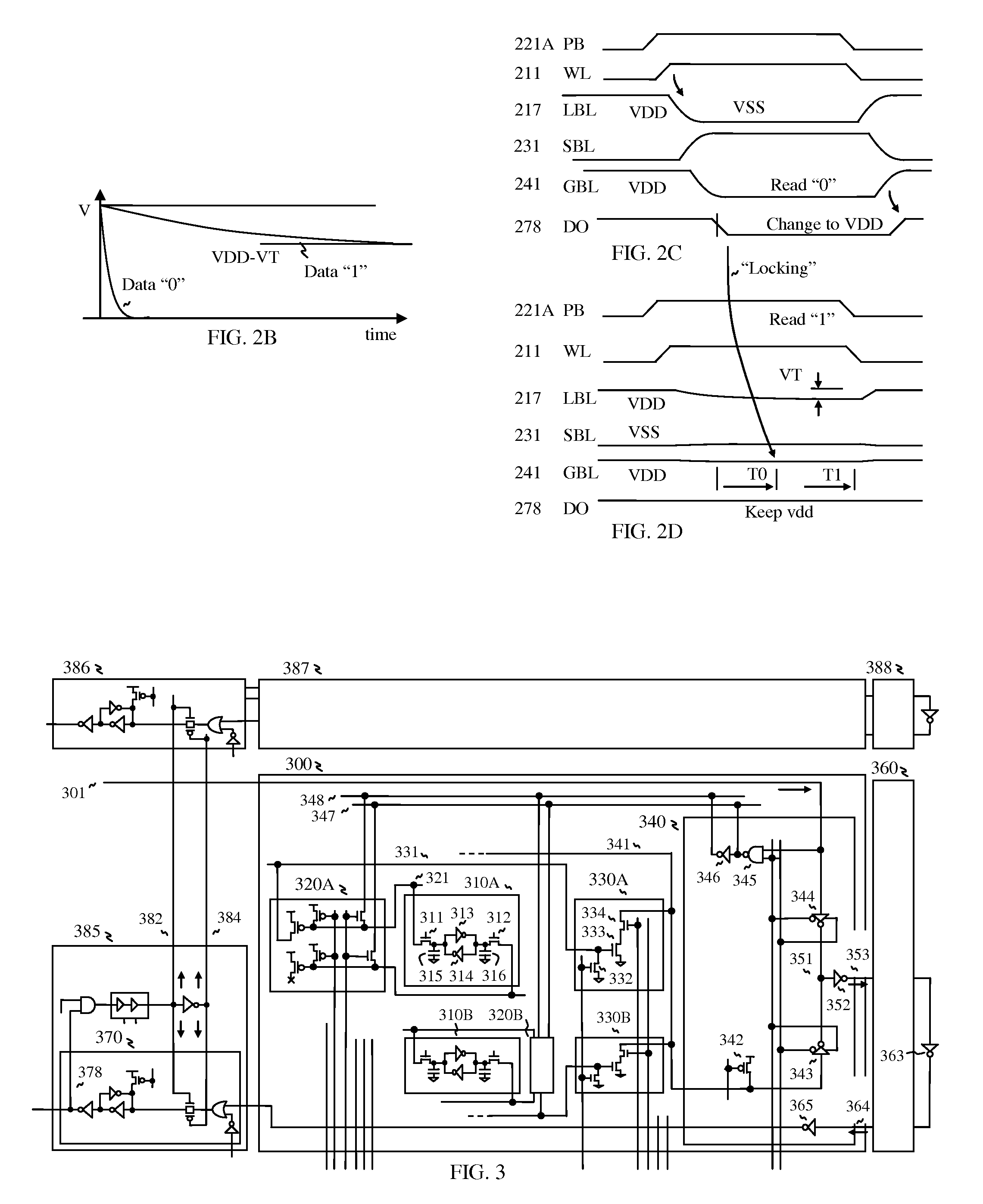
[0010]For realizing low power SRAM, bit lines are multi-divided so that multi-stage sense amps are used to read the memory cell through the divided local bit lines. In particular, amplifying transistors of the sense amps are composed of relatively long channel transistors than those of pre-charge transistors in order to reduce turn-off current, which reduces power consumption. Furthermore, the multi-stage sense amps are composed of dynamic circuits for eliminating penetration current when reading, wherein the multi-stage sense amps include a first dynamic circuit serving as a local sense amp for reading the memory cell through a local bit line, a second dynamic circuit serving as a segment sense amp for reading the local sense amp through a segment bit line, and a first tri-state inverter serving as an inverting amplifier of a global sense amp for reading the segment sense amp through a global bit line, while a second tri-state inverter is used for bypassing an output from a previous memory block, which configures a data transfer circuit. The dynamic circuits are also useful to reduce operating voltage for realizing low power consumption, because the dynamic circuits are turned on around threshold voltage of MOS transistor for detecting whether an amplify transistor is turned on or not. With multi-stage sense amp, access time is improved because each sense amp drives lightly loaded bit lines, such that the memory cell drives lightly loaded local bit line, the local sense amp drives the segment bit line for transferring a read output to the segment sense amp, the segment sense amp drives the global bit line for transferring the read output to the global sense amp, and the global sense amp drives a common line of the data transfer circuit for transferring the read output to an output latch circuit.

Problems solved by technology

Furthermore, heavily loaded bit lines may flip unselected memory cells during read and write operation.
As a result, the transistors in the memory cell are bigger than minimum feature size within the fabrication process limit typically, which increases the chip area.
Conventionally, the write data line pair is heavily loaded with no buffers, so that the write data lines always drive full length of the memory block, which increases driving current and RC delay time.
Furthermore, the read data line is also heavily loaded for connecting to multiple memory blocks with no buffers, which increases driving current and RC delay time as well.
However, each memory segment including the bit line comprises more circuits such as a cross-coupled keeper transistor circuit, a local read amplifier circuit, pre-charge transistors, and transfer transistors, which increases chip area.
And one more prior art is shown, “A low power SRAM Using Hierarchical Bit Line and Local read amplifiers”, Yang et al, IEEE Journal of Solis-State Circuits, Vol. 40, No. 6, June 2005, such that the local read amplifier improves write operation, but it does not improve read operation because the local read amplifier is not activated during read cycle.
As a result, the access time is still slow and area may be increased more.
If the operation voltage further drops, the amount of charge stored in the storage node drops, so that the potential fluctuation of the storage node due to alpha rays cannot be suppressed, deteriorating the soft error resistance.
However, these approaches solve only memory cell portion, but they don't suggest any new improvements with peripheral circuits such as sense amps, in order to miniaturize the memory cell.

Method used


Image

  • High speed SRAM
  • High speed SRAM
  • High speed SRAM

Examples


Embodiment Construction

)

[0032]Reference is made in detail to the preferred embodiments of the invention. While the invention is described in conjunction with the preferred embodiments, the invention is not intended to be limited by these preferred embodiments. On the contrary, the invention is intended to cover alternatives, modifications and equivalents, which may be included within the spirit and scope of the invention as defined by the appended claims. Furthermore, in the following detailed description of the invention, numerous specific details are set forth in order to provide a thorough understanding of the invention. However, as is obvious to one ordinarily skilled in the art, the invention may be practiced without these specific details. In other instances, well-known methods, procedures, components, and circuits have not been described in detail so that aspects of the invention will not be obscured.

[0033]The present invention is directed to high speed SRAM as shown in FIG. 2A, wherein a memory bl...


PUM


Abstract

High speed SRAM is realized such that a first dynamic circuit serves as a local sense amp for reading a memory cell through a lightly loaded local bit line, a second dynamic circuit serves as a segment sense amp for reading the local sense amp, and a tri-state inverter serves as an inverting amplifier of a global sense amp for reading the segment sense amp. When reading, a voltage difference in the local bit line is converted to a time difference for differentiating low data and high data by the sense amps for realizing fast access with dynamic operation. Furthermore, a buffered data path is used for achieving fast access and amplify transistor of the sense amps is composed of relatively long channel transistor for reducing turn-off current. Additionally, alternative circuits and memory cell structures for implementing the SRAM are described.

Description

FIELD OF THE INVENTION[0001]The present invention relates generally to integrated circuits, in particular to high speed SRAM (Static Random Access Memory).BACKGROUND OF THE INVENTION[0002]For its high-speed and short cycle time, the SRAM (Static Random Access Memory) is utilized extensively as a cache memory in computer systems and network systems. Furthermore, the SRAM is simple to use with no refresh operation. As such, the SRAM constitutes a key component that holds sway on the speed and performance of the computer systems and other systems. Efforts of research and development have been under way primarily to boost the operating speed of the memory.[0003]FIG. 1 illustrates a circuit diagram of a conventional SRAM including memory segment, a write circuit and a sense amplifier, as published, U.S. Pat. No. 4,712,194 and No. 6,075,729. The memory block 100 includes memory cells 110, 111, 112 and 113 having six transistors. The memory cells are connected to bit lines 121, 122, 123 an...

Claims


Application Information

Patent Timeline
Patent Type & Authority Applications(United States)
IPC IPC(8): G11C15/00G11C7/00
CPCG11C7/1048G11C15/04G11C11/419G11C7/18
Inventor KIM, JUHAN
Owner FRONTEON
Learn More