
Secondary Battery with a Spirally-Rolled Electrode Group

a technology of spirally rolled electrodes and secondary batteries, which is applied in the direction of wound/folded electrode electrodes, cell components, sustainable manufacturing/processing, etc., can solve the problems of short circuit, difficult spot welding with the cover body, and short circuit, so as to remove the necessity of welding and the process is made simple.

Inactive Publication Date: 2010-03-04
JAPAN CAPACITOR IND
View PDF9 Cites 2 Cited by
  • Summary
  • Abstract
  • Description
  • Claims
  • Application Information

AI Technical Summary

Benefits of technology

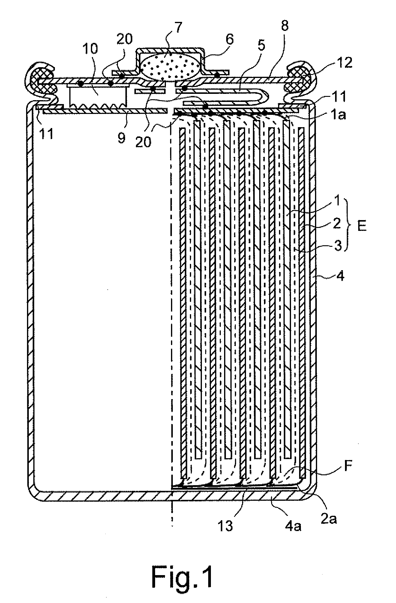
[0015]In the battery with the spirally-rolled electrode group, although in general, the negative electrode contacts with the bottomed cylindrical can that also functions as the negative electrode terminal, since the positive electrode is only connected to the cover body that also functions as the positive electrode terminal by the metal lead plate, the above mentioned improvement in the metal lead plate is indeed effective for reducing the internal impedance of the battery.
[0020]The present invention relates both to generally used D-sized batteries and Cs-sized batteries and to the batteries with improved reliability (Japan unexamined laid-open patent publication 2006-12801) of preventing micro short circuit caused by the falling-off of the active material powders by bending the metal exposure portion provided at the end surface of the positive and negative electrode of the electrode group together with the separator to make it bag-like as already suggested by the inventors, and the present invention provides the structure with improved power characteristics of these.
[0022]For information, in accordance with this, the lead of the negative electrode that is in the opposite side to the lead of the positive electrode of the electrode group also receives the pressure, the structure is made to be flexible to receive the pressure and the process is made to be simple so that it can remove the necessity of welding to the can.

Problems solved by technology

However, the non-patent document 1 has problems that with the thick metal lead, bending becomes difficult in inserting the cover body to the bottomed cylindrical can, with the wide metal lead, there lies a risk of short circuit caused by contacting with the can, and with the short scaled metal lead, spot welding with the cover body becomes difficult and the like and defective rate increases during mass production.
The prior art 2 also has problems that the metal lead plate contacts with the can thereby generating the risk of short circuit when the cover body that is welded and connected to the two metal lead plates is inserted in the can, and the defective rate increases during mass production.
The non-patent documents 1 and 2 also have problems similar to those of the prior art 2 although the impedance can greatly be reduced and they also have problems that the electrolyte spews out due to heating or the welding becomes uneven when high current of pulse or AC flows is applied to the battery after sealing with the cover body.

Method used


Image

  • Secondary Battery with a Spirally-Rolled Electrode Group
  • Secondary Battery with a Spirally-Rolled Electrode Group
  • Secondary Battery with a Spirally-Rolled Electrode Group

Examples


example 1

[0040]A mixture of generally used nickel hydroxide (Ni(OH)2) powder and cobalt oxide powder with a weight ratio of 96:4 was kneaded with an aqueous solution of fluorine resin powder (1 wt. %) and carboxymethyl cellulose (0.3 wt. %), which was coated on an electrode substrate made of a three dimensional nickel foil (hereinafter called 3DF as in Japan unexamined laid open publication 2002-198055 already filed by the inventors). After dried, it was pressurized thereby obtaining a nickel positive electrode with an average filling density of 650 mAh and a thickness of 0.3 mm. Next, this electrode was cut into 43 mm in width and 910 mm in length, followed by removing the above mentioned coating material only by 4 mm in width along the long scale end surface of one side thereby forming a metal exposure portion and then, the positive electrode with a theoretical capacity of about 6.6 Ah processed for a cylindrical sealed D-sized battery with a diameter of about 32 mm was obtained.

[0041]The ...

example 2

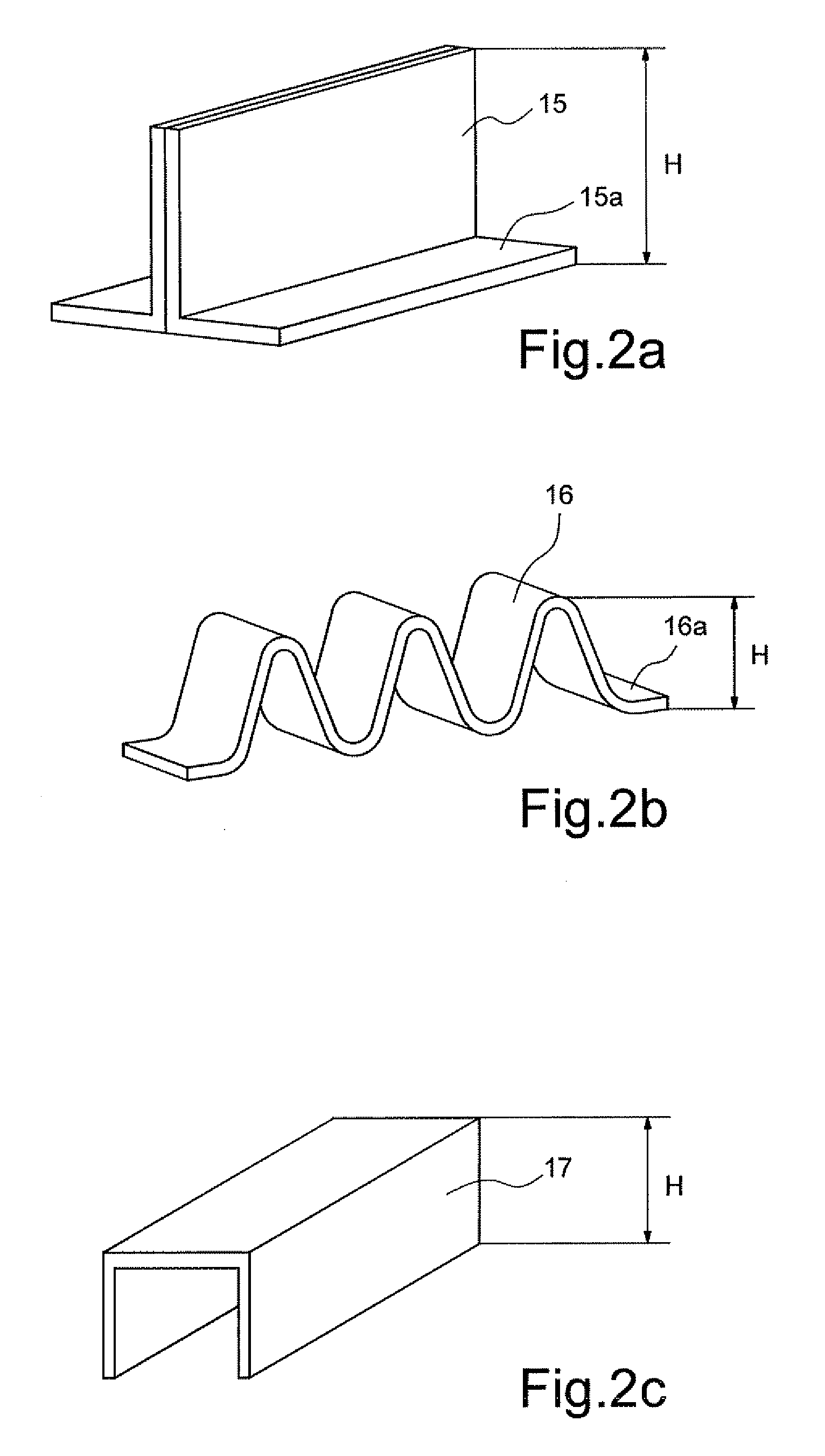
[0048]The welding pieces 15a of the metal presser with a height of 3.5 mm as shown in FIG. 2a in Example 1 are welded to the cover body that corresponds to the position shown in FIG. 3 and with the same structure and the same formation as in Example 1, D-sized batteries are obtained with a height of 51 mm. When 5 cells of these batteries were under 10 C discharge as described in Example 1, the similar voltage as in the case of L in Example 1 was obtained.

example 3

[0049]Similar D-sized batteries are obtained by employing the similar structure as in Example 1 but without welding the metal-made current collecting plates 9 and 13 of the positive electrode 1 and the negative electrode 2 to the respective metal exposure portions. In this case, although the discharge voltage was very slightly reduced, it was much higher than M and N in Example 1 and rather it showed the value closer to L in Example 1.


PUM


Abstract

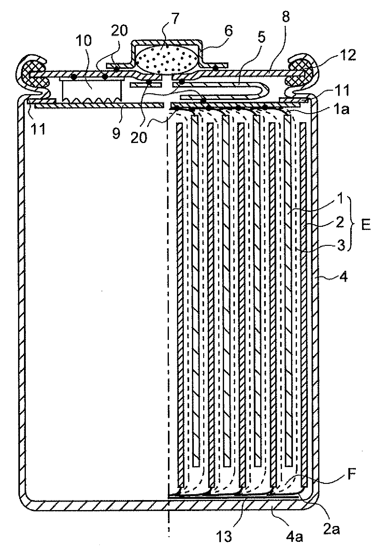
An electrode group E in which a positive electrode 1 and a negative electrode 2 are spirally-rolled interposing a separator 3 is contained in a bottomed cylindrical can 4. A metal exposure portion 1a provided on an end surface of the positive electrode 1 of the electrode group E or a metal-made current collecting plate 9 electrically connected to the metal exposure portion 1a (called a current collecting portion of a positive electrode) and a cover body 8 also functioning as a positive electrode terminal are electrically connected by a metal lead plate 5. One or more electrolyte resistant metal pressers 10 are arranged and electrically connected between the current collecting portion of the positive electrode and the cover body 8. The electrode group E is applied pressure by the cover body 8 and the bottom portion 4a of the bottomed cylindrical can 4.

Description

CROSS-REFERENCE TO RELATED APPLICATION[0001]This application claims the benefit of priority based on Japanese Patent Application No. 2008-224494, the entire same contents of which are incorporated by reference herein.BACKGROUND OF THE INVENTION[0002]1. Field of the Invention[0003]The present invention relates to a secondary battery with improved internal impedance having a spirally-rolled electrode group and in particular, the present invention relates to a secondary battery for high-rate discharge.[0004]2. Description of the Prior Art[0005]In recent years, for the purpose of mitigating global environmental issues and energy issues, introducing hybrid electric vehicles (HEV) and electric vehicles (EV) and expanding the market share thereof has been drawing attention as effective means for saving oil consumption to about a half. In particular, HEV having already been put into practical use, presently, with nickel-hydrogen batteries (Ni / MH batteries) mounted, are expanding its market ...

Claims


Application Information

Patent Timeline
IPC IPC(8): H01M6/10H01M50/469H01M50/538
CPCH01M2/0413H01M2/18H01M10/0468H01M10/0413H01M10/0431H01M2/263Y02E60/10H01M50/171H01M50/538Y02P70/50H01M50/469H01M50/531H01M4/04H01M50/466
Inventor MATSUMOTOZHOU, HUAKUWANA, KOJI
Owner JAPAN CAPACITOR IND
Learn More