Membrane support module for permeate separation in a fuel cell

a fuel cell and membrane support technology, applied in the direction of membranes, separation processes, electrochemical generators, etc., can solve problems such as fatigue and ruptur

Active Publication Date: 2010-03-18
SILICON VALLEY BANK
View PDF26 Cites 73 Cited by
  • Summary
  • Abstract
  • Description
  • Claims
  • Application Information

AI Technical Summary

Benefits of technology

[0024]In another embodiment, the subject technology is directed to a permeate assembly for separating a permeate gas from a pressurized feed mixture. The permeate assembly includes a support frame having a frame perimeter that defines a central aperture, a porous spacer in the central aperture, a microscreen element having a first surface compressed against the support frame and the porous spacer and a second planar surface opposing the first surface, the microscreen element having a non-porous perimeter in mating contact with the frame perimeter and defining a plurality of transverse passages from the second surface to the first surface, the transverse passages being in ...

Problems solved by technology

Additionally, gaps and/or discontinuities are often formed by the support structure so that the membrane deforms into these discontinuities and locations of...

Method used


Image

  • Membrane support module for permeate separation in a fuel cell
  • Membrane support module for permeate separation in a fuel cell
  • Membrane support module for permeate separation in a fuel cell

Examples


first embodiment

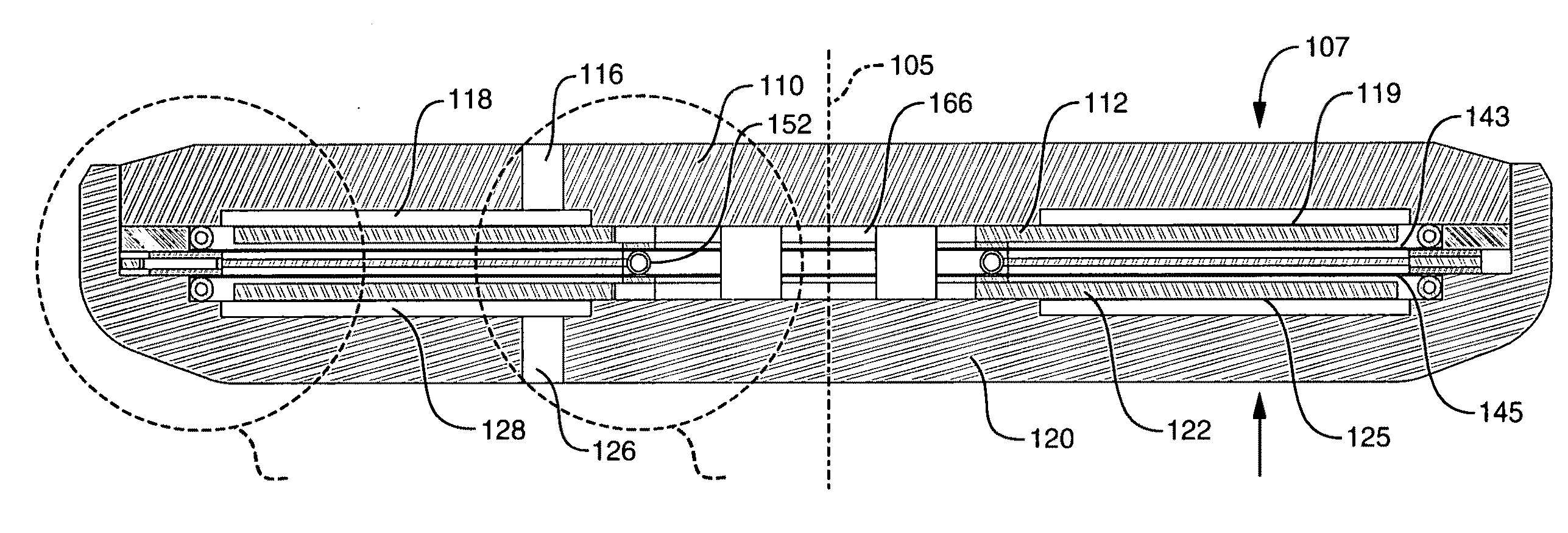
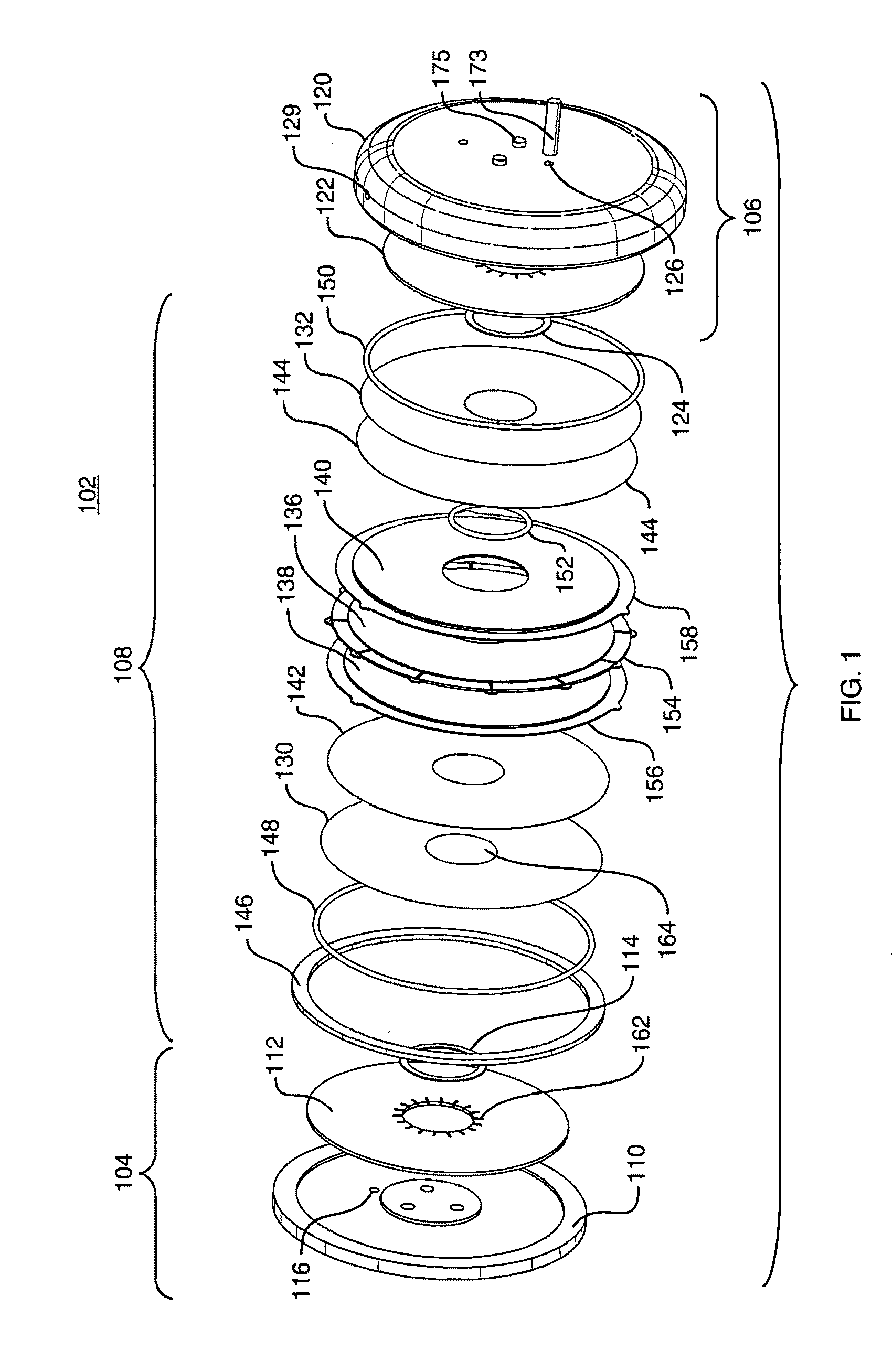
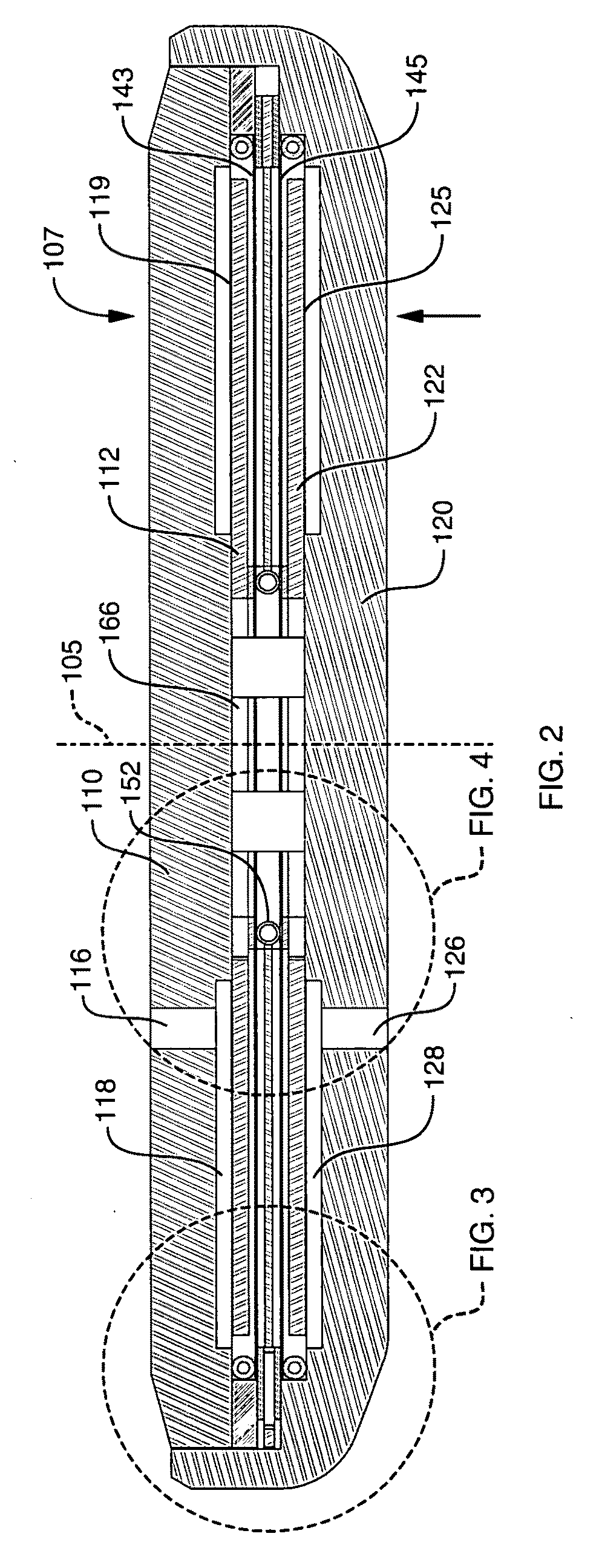
[0045]Referring to FIGS. 1-8, a gas separation unit 102 in according to the subject technology includes an input manifold 104 for receiving a gaseous mixture into the gas separation unit through an input port 116, an output manifold 106 for exhausting any remaining gaseous mixture out of the gas separation unit through an output port 126 and a permeate assembly 108 disposed between the input manifold 104 and the exhaust manifold 106 for separating permeate gas out from the gaseous feed mixture and for exhausting the permeate gas separated out there from out of the gas separation unit through a permeate output port 129. The gas separation unit 102 has a circular cross-section centered by a central axis 105 and has a transverse thickness 107.

[0046]Referring now to FIGS. 2 and 3, the input manifold 104 receives the gaseous feed mixture through the intake port 116 and delivers the gaseous mixture into a first chamber 118. The first chamber 118 includes a first portion disposed between a...

third embodiment

[0095]Referring now to FIGS. 13-14, a gas separation unit 300 in accordance with the subject technology includes a single permselective membrane 318 disposed in mating contact with a single microscreen element 326. The gas separation unit 300 has a rectangular cross-section with a longitudinal length shown in section view in FIG. 13, which shows the flow pathway of a gaseous feed mixture, and a transverse width shown in section view in FIG. 14, which shows the flow pathway of a permeate gas separated out from the gaseous mixture.

[0096]An input manifold comprises a top plate 310 and a pair of feed frames 244 configured as described above. The feed frames 244 form a left end chamber 330 a first chamber 302 and a right end chamber 332. A gaseous feed mixture, that includes a permeate gas, enters into the left end chamber 330 through an input port 304, passes from the left end chamber 330 to the first chamber 302 and then to the right end chamber 332, where the gaseous mixture can exit ...


PUM

PropertyMeasurementUnit
Thicknessaaaaaaaaaa
Thicknessaaaaaaaaaa
Thicknessaaaaaaaaaa

Abstract

A gas separation unit 102, 200, 300 for permeating a gas out from a pressurized feed mixture includes an input manifold 104, 204, an exhaust manifold, 106, 206 and a permeate assembly 108, 208, 303. The permeate assembly supports one or more permselective foils 130, 132, 218, 232, 318 over a hollow cavity 134, 272, 306 supported by a microscreen element 142, 144, 228, 230, 326. The microscreen element includes non-porous perimeter walls 190, 192, 278 supported on a frame surface and a porous central area 194, 280 supported over the hollow cavity. A porous spacer 138, 140, 174, 234 disposed inside the hollow cavity structurally supports the entire microscreen surface spanning the hollow cavity while also providing a void volume for receiving fluid passing through the porous central area and for conveying the fluid through the hollow cavity.

Description

BACKGROUND OF THE INVENTION[0001]The subject technology relates to a method and apparatus for supporting a membrane for gas separation for use with a fuel cell and like devices. More specifically, a metal foil permselective membrane is supported over an open cavity by a planar microscreen element that includes a thin metal sheet form with a non-porous perimeter wall surrounding a perforated or porous central area that is sized to match the dimensions of the open cavity.[0002]Fuel cells are electrochemical devices that produce direct current (DC) electricity by the reaction of a fuel with an oxidant, typically producing byproducts of heat and water. Common fuels are hydrogen, methanol, and carbon monoxide. The most common oxidant is oxygen, either in a relatively pure form or from ambient air. Fuel cells contain an anode, a cathode, and an electrolyte barrier between the anode and cathode. The fuel is introduced at the anode and the oxidant is introduced at the cathode. The electroly...

Claims


Application Information

Patent Timeline
IPC IPC(8): B01D53/22
CPCB01D53/22B01D63/082B01D2255/1023B01D2256/16H01M8/0662B01D2257/50B01D2257/80B01D2313/14B01D2313/20B01D2257/102C01B3/505Y02E60/50
Inventor EDLUND, DAVIDOSENAR, PAULPALUMBO, NATHANREZAC, RONALDSTEINBRONER, MATT
Owner SILICON VALLEY BANK
Why Eureka
Try Eureka