Carbon fiber reinforced carbon matrix composite for brake pad back plate

a technology of carbon fiber reinforced carbon matrix and brake pad back plate, which is applied in the field of brake pad assembly improvement, can solve the problems of loss of weight that is most susceptible, and loss of deceleration ability

Active Publication Date: 2010-03-18
CMBF PROD INC
View PDF32 Cites 36 Cited by
  • Summary
  • Abstract
  • Description
  • Claims
  • Application Information

AI Technical Summary

Benefits of technology

[0012]The following presents a simplified summary of the invention in order to provide a basic understanding of some example aspects of the invention. This summary is not an extensive overview of the invention. Moreover, this summary is not intended to

Problems solved by technology

Depending on the rate of heat introduced into the braking system compared to the rate of heat expelled from the system, the temperatures of disc brake components may be elevated to a level surpassing their designed operational limits, thus leading to failure.
Thus, if the brake fluid temperature reaches its boiling point and vaporizes during use, the result is a partial or complete loss in the ability to transmit force to the brake pad which can result in a loss of deceleration capability.
Since unsprung weight is not s

Method used


Image

  • Carbon fiber reinforced carbon matrix composite for brake pad back plate
  • Carbon fiber reinforced carbon matrix composite for brake pad back plate
  • Carbon fiber reinforced carbon matrix composite for brake pad back plate

Examples


example 1

[0079]The herein described example brake pad assembly was manufactured (see FIG. 6) in accordance with an automotive racing application in mind. The particular racing application experiences relatively high speeds and requires aggressive deceleration. Therefore, the properties desired of the brake pad in this application generally include: high coefficient of friction, good wear resistance, high-temperature frictional stability, low mass, ability to withstand the forces induced under braking, ability to resist thermal degradation at elevated temperatures, and preferential conduction of heat away from the caliper pistons. The example method steps are illustrated in FIG. 6 in process flowchart 600 that begins at 601. A simulation of these conditions was tested on an inertia brake dynamometer with the parameters as described in Table 4 and test results provided in Table 5, and FIG. 9.

TABLE 4ItemTesting ConditionTesting MethodDeceleration test under constant deceleration rateInertial Ma...

example 2

[0095]Similar to Example 1, the herein described brake pad of Example 2 was manufactured (see FIG. 6) in accordance with an automotive racing application in mind and was designed for enhanced durability. Therefore, the same requirements and desired properties of Example 1 are realized in this example. The manufacturing steps are illustrated in FIG. 6 in process flow chart 600 that begins with 601. The brake pads embodying Example 2 were tested on an inertia brake dynamometer with the parameters described in Table 6.

TABLE 6ItemTesting ConditionTesting MethodDeceleration test under constant deceleration rateInertial Mass 43.376 slug-ft2Rolling Radius 13.750 in.Brake RotorGrey Cast Iron, Brembo 099229.10Brake Pad ShapeHawk Performance HB109Brake Pad Area12.4261 in2Caliper TypeAP opposing 6-piston CP5810-5S0MPiston Area per side 4.295 in2Effective Radius 5.322 in.Initial Velocity  1830 rpm (simulated 150 mph)Final Velocity  1100 rpm (simulated 90 mph)Brake Initiation Temp.900° F.Deceler...


PUM

PropertyMeasurementUnit
Poweraaaaaaaaaa
Poweraaaaaaaaaa
Poweraaaaaaaaaa

Abstract

A brake pad assembly is provided, including a friction lining providing a wear surface for contacting a brake rotor and a back plate coupled to the friction lining. The back plate is made of a carbon fiber reinforced carbon matrix composite. In one example, a majority of the carbon fibers of the back plate are oriented in a x-y in-plane direction resulting in a structure where the thermal conductivity is at least 2 times greater in the x-y in-plane direction versus a z through-plane direction. In another example, the back plate is provided as at least one sheet of a carbon fiber reinforced carbon matrix composite. A method of manufacturing the brake pad assembly is also provided.

Description

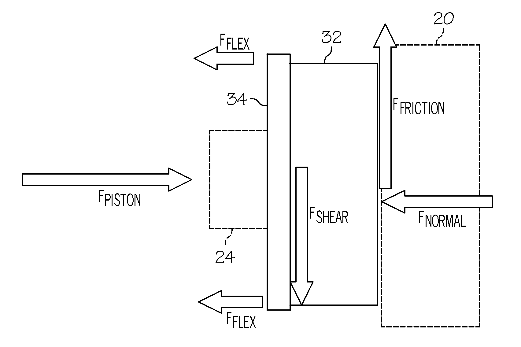
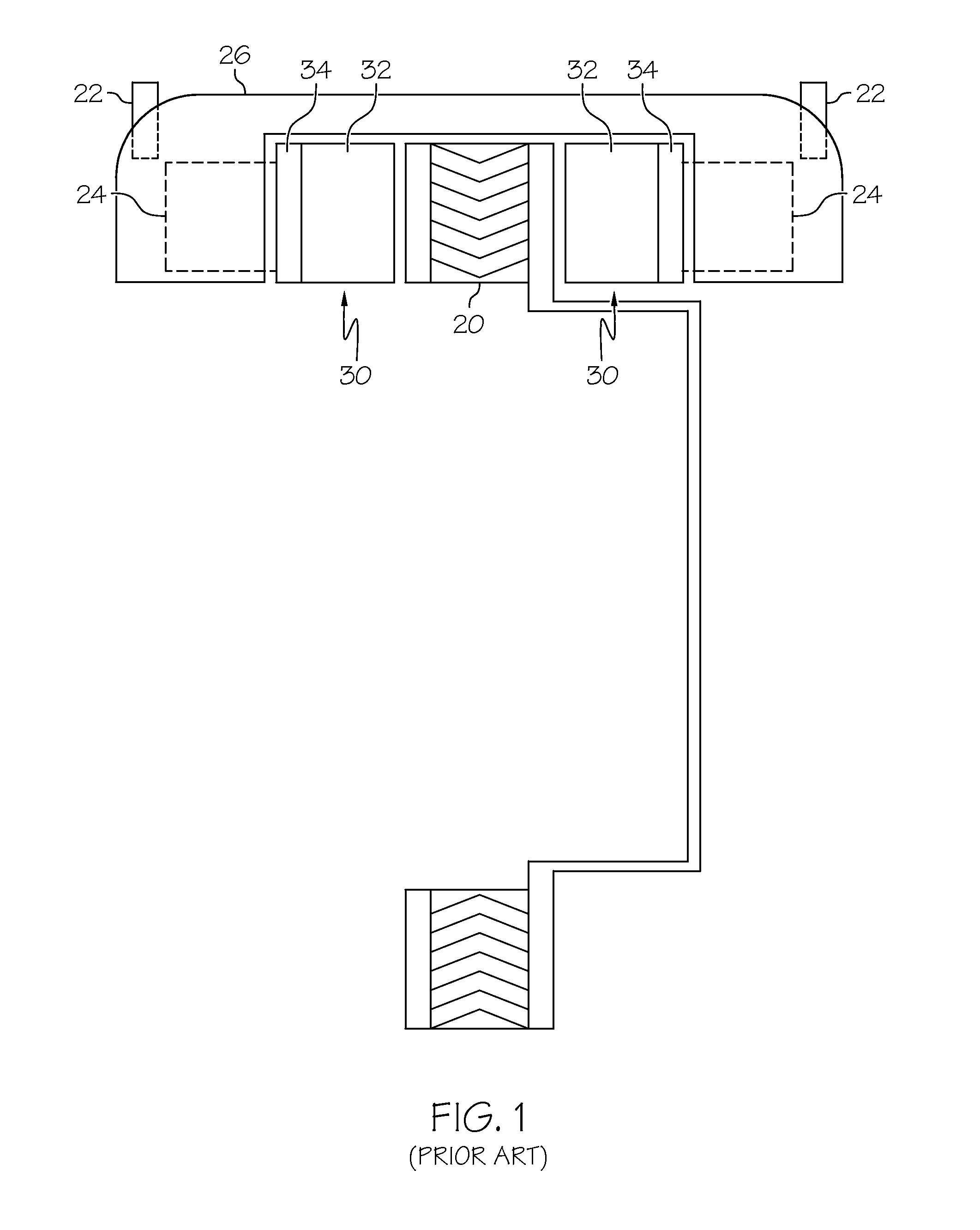
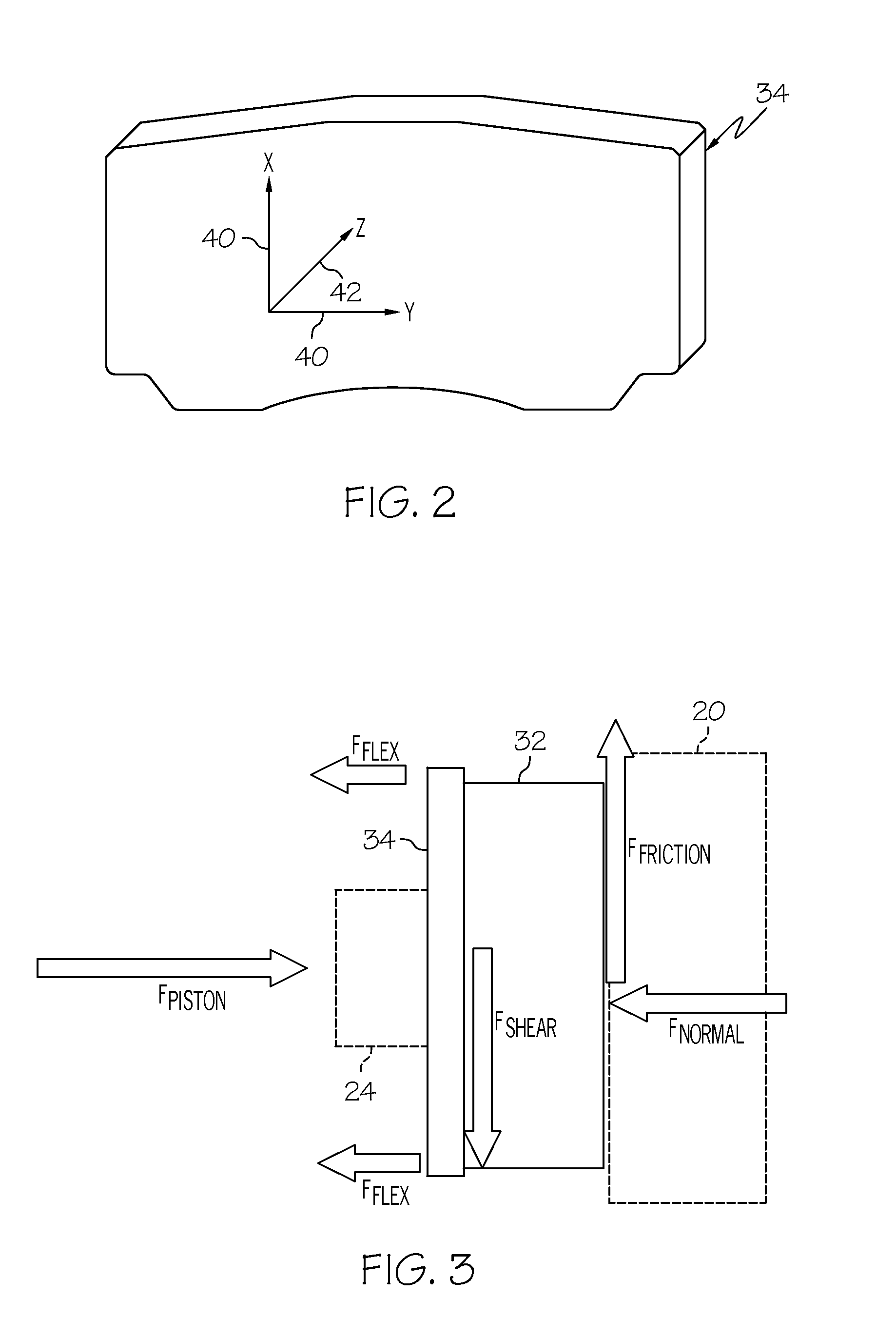
CROSS-REFERENCE TO RELATED APPLICATIONS[0001]This application claims the benefit of U.S. Provisional Application No. 61 / 098,132, filed Sep. 18, 2008, the entire disclosure of which is hereby incorporated herein by reference.FIELD OF THE INVENTION[0002]The present invention generally relates to brake pads and, in particular, to improvements in brake pad assemblies.BACKGROUND OF THE INVENTION[0003]Many vehicles today, such as automobiles, motorcycles, trucks, trains, and aircraft, employ a caliper-disc brake assembly as the primary mechanism for deceleration. The caliper-disc brake system (FIG. 1, prior art) generally includes a pair of brake pads 30 arranged on opposite sides of the annular surfaces of a rotating disc, or rotor 20 coupled to a wheel or other rotating structure. The rotor is disposed between a brake actuating mechanism, of which the brake actuating mechanism is provided outside of the pair of brake pads 30. The brake actuating mechanism generally includes a caliper 26...

Claims


Application Information

Patent Timeline
IPC IPC(8): F16D69/00B23P11/00
CPCF16D2069/0483F16D65/092F16D2069/0433Y10T29/49826F16D2069/045F16D69/04F16D2069/0441F16D2200/0052F16D2069/0491F16D2200/0069F16D2250/0069F16D2069/0466
Inventor GILBOY, LAWRENCE FRANKWOLF, RICHARD A.MOREY, AARON M.
Owner CMBF PROD INC
Why Eureka
Try Eureka