Charged particle beam apparatus

Active Publication Date: 2010-03-18
HITACHI HIGH-TECH CORP
View PDF25 Cites 45 Cited by
  • Summary
  • Abstract
  • Description
  • Claims
  • Application Information

AI Technical Summary

Benefits of technology

[0018]With the present invention, it is possible to implement a charged particle beam apparatus capable of rendering high defect-detection sensitivity compatib

Problems solved by technology

Furthermore, unless misalignment of the multipoles, and design error are controlled to a minimum, and symmetry of the multipoles is sufficiently maintained, aberration correction cannot be im

Method used


Image

  • Charged particle beam apparatus
  • Charged particle beam apparatus
  • Charged particle beam apparatus

Examples


first embodiment

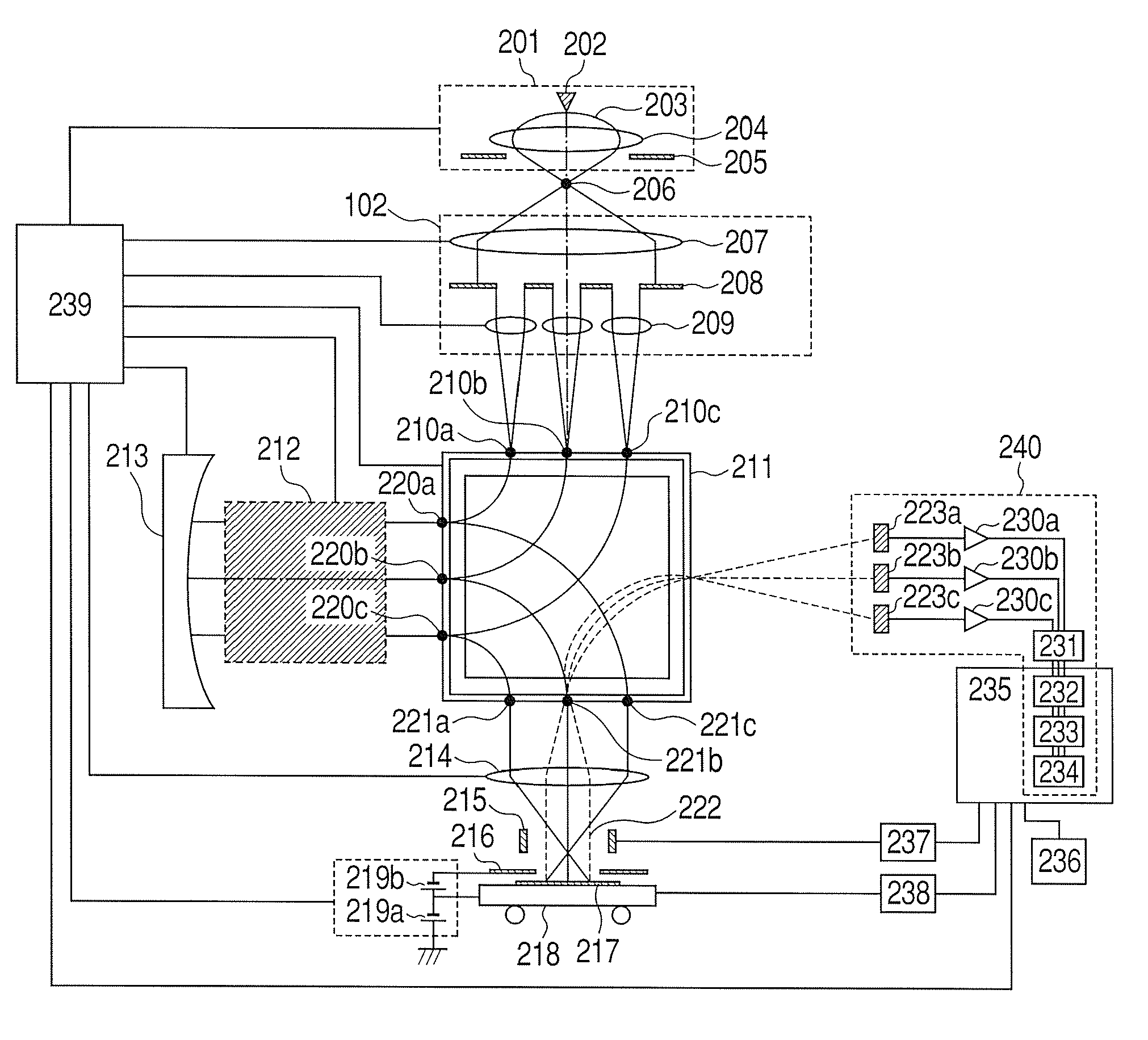
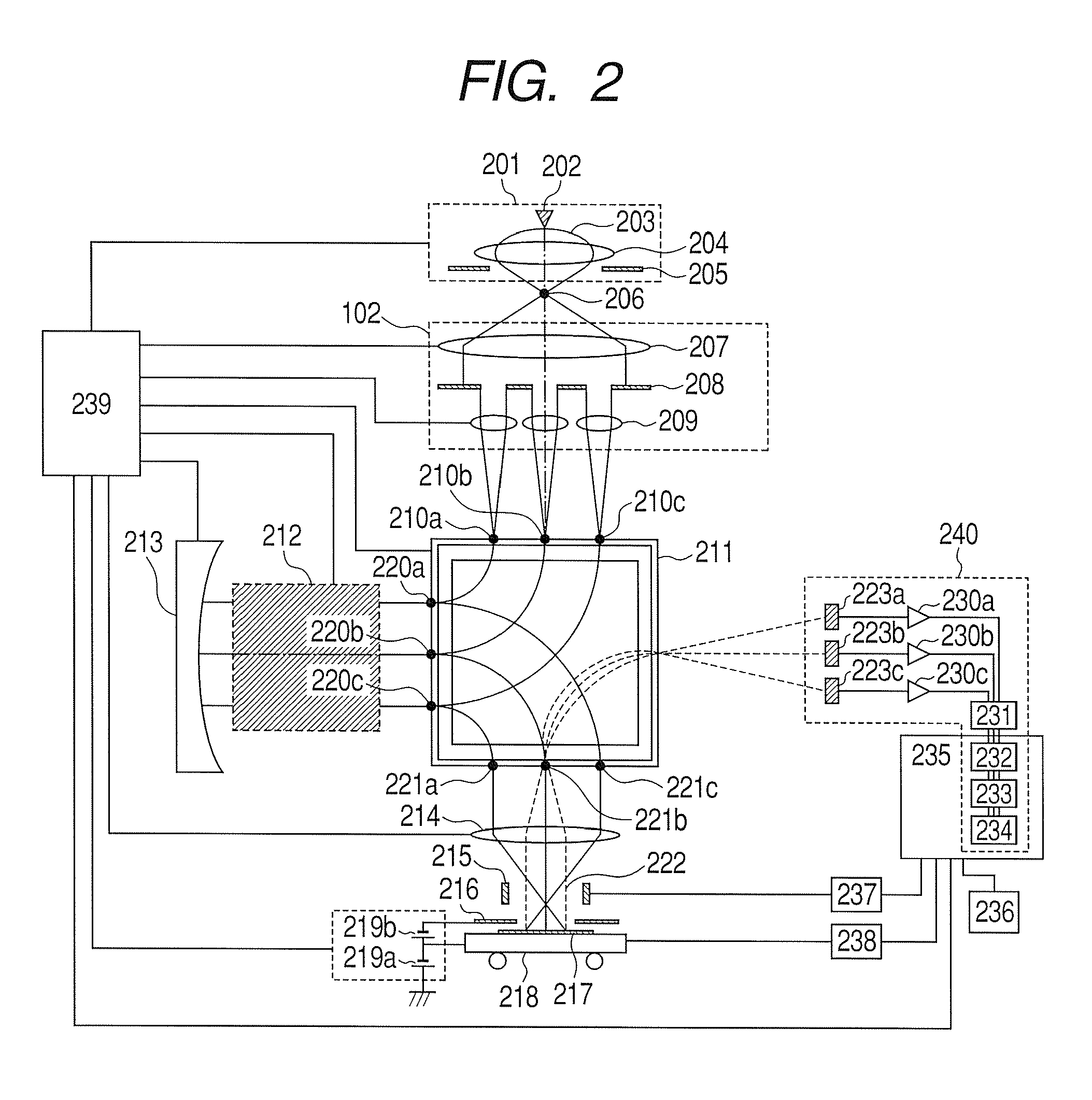
[0033]FIG. 2 is a view showing a schematic configuration of a multi-beam type electron beam inspection apparatus according to the first embodiment of the invention.

[0034]First, a makeup of the apparatus is described hereinafter. An electron gun 201 is comprised of a cathode 202 made of material low in work function, an anode 205 higher in potential than the cathode 202, and an electromagnetic lens 204 for superimposing a magnetic field on an accelerating electric field formed between the cathode and the anode. With the present embodiment, use is made of a Schottky type anode capable of easily obtaining large current, and stable in electron emission. A multi-beams forming unit 102, and a beam separator 211 are disposed in a direction downstream from the electron gun 201, in which a primary beam 203 is pulled out of the electron gun 201. Herein, with the present embodiment, the multi-beams forming unit 102 is comprised of a collimator lens 207, an aperture array 208 wherein plural ape...

second embodiment

[0058]With the first embodiment of the invention, the off-axial aberration corrector shown in FIG. 3 has the configuration wherein the electrostatic mirror is disposed at the position of the symmetry plane 307b. In contrast, with a second embodiment of the invention, there is adopted a configuration wherein an electrostatic mirror is disposed at the respective positions of the symmetry planes 307b, and 307c of the off-axial aberration corrector shown in FIG. 3, thereby disposing a combination of the aberration corrector, and the electrostatic mirror at two locations.

[0059]FIG. 6 is a schematic view of a multi-beam type electron beam inspection apparatus according to the second embodiment of the invention. In FIG. 6, placement of constituent elements including an electron gun 201, a cathode 202, an anode 205, an electromagnetic lens 204, a collimator lens 207, an aperture array 208, and a lens array 209 is turned clockwise through 90 degrees from placement of like constituent element...

third embodiment

[0075]With the first embodiment, since the position of the electrostatic octupole field strength 303h in the aberration corrector, shown in FIG. 3, coincides with the position of the electrostatic mirror 213, an electrostatic octupole field strength corresponding to the electrostatic octupole field strength 303h is not disposed. In contrast, with the second embodiment, there is shown the method for superimposing the electrostatic mirror field on the multipole fields by devising a novel configuration for the electrostatic mirror 602a although the respective positions of the electrostatic quadrupole field strength 302d, and the electrostatic octupole field strength 303d, in the off-axial aberration corrector shown in FIG. 3, coincide with the position of the electrostatic mirror 602a. Accordingly, with the present embodiment, there is shown a method for superimposing the electrostatic octupole field strength 303h on the electrostatic mirror 213 in the configuration of the apparatus ac...


PUM


Abstract

With a multi-beam type charged particle beam apparatus, and a projection charged particle beam apparatus, in the case of off-axial aberration corrector, there is the need for preparing a multitude of multipoles, and power supply sources in numbers corresponding to the number of the multipoles need be prepared. In order to solve this problem as described, a charged particle beam apparatus is provided with at least one aberration corrector wherein the number of the multipoles required in the past is decreased by about a half by disposing an electrostatic mirror in an electron optical system.

Description

CLAIM OF PRIORITY[0001]The present application claims priority from Japanese patent application JP 2008-234191 filed on Sep. 12, 2008, the content of which is hereby incorporated by reference into this application.FIELD OF THE INVENTION[0002]The invention relates to a charged particle beam apparatus making use of a charged particle beam, such as a charged particle beam inspection apparatus, a charged particle beam measuring instrument, a charged particle beam lithography apparatus, and so forth.BACKGROUND OF THE INVENTION[0003]In a process of manufacturing a semiconductor, and a magnetic disc, use is made of a charged particle beam measuring instrument wherein a specimen is irradiated with a charged particle beam (hereinafter referred to as a primary beam), such as an electron beam, an ion beam, and so forth, to acquire a signal of a secondary charged particle (hereinafter referred to as a secondary beam) such as a secondary electron emitted, and so forth, thereby measuring a shape ...

Claims


Application Information

Patent Timeline
IPC IPC(8): H01J3/16
CPCH01J37/1472H01J2237/1534H01J2237/151H01J37/153
Inventor ENYAMA, MOMOYOOHTA, HIROYAKAMIMURA, OSAMU
Owner HITACHI HIGH-TECH CORP
Why Eureka
Try Eureka