Alkali metal seawater battery

Active Publication Date: 2010-03-18
FIELD UPGRADING USA INC
View PDF99 Cites 35 Cited by
  • Summary
  • Abstract
  • Description
  • Claims
  • Application Information

AI Technical Summary

Benefits of technology

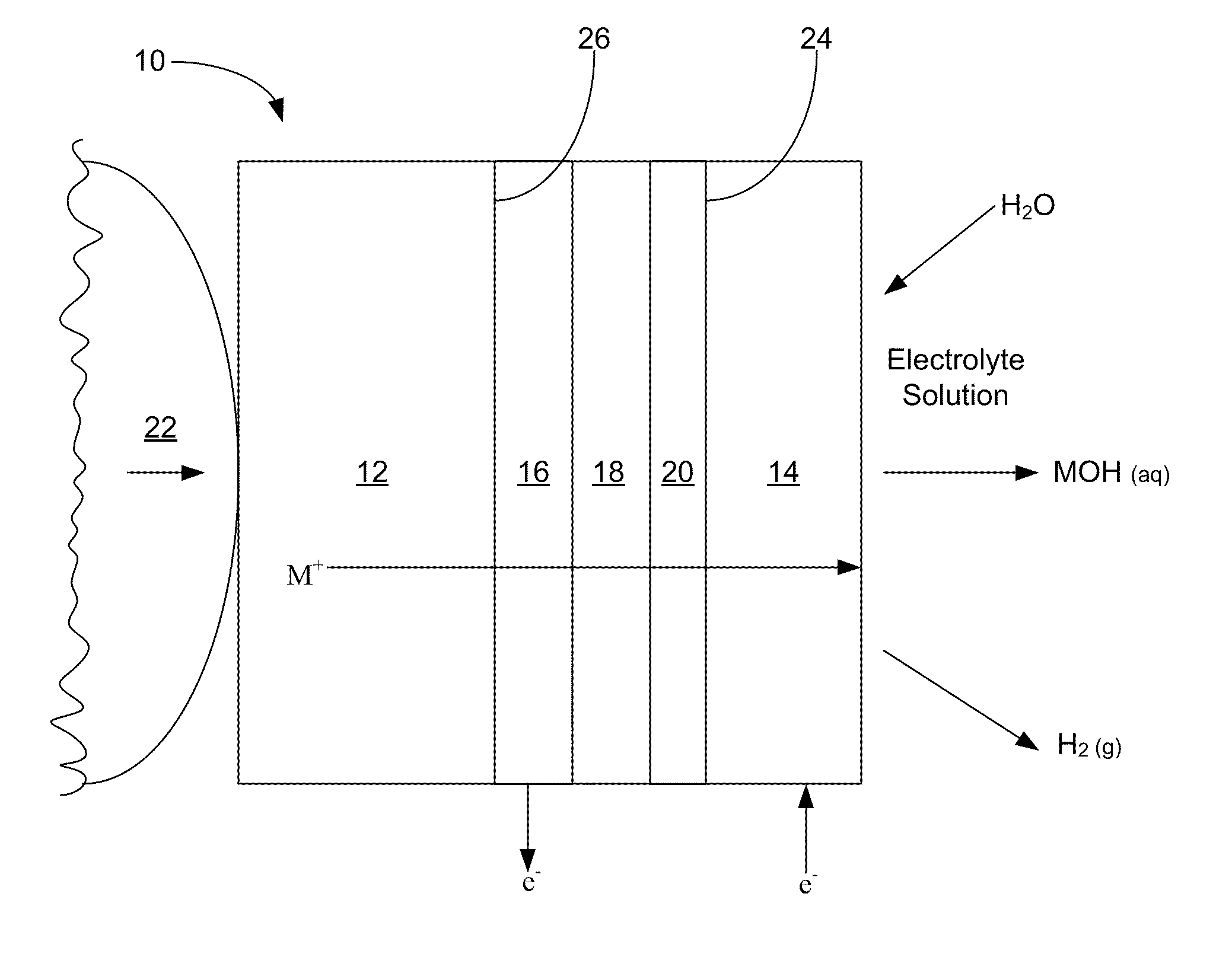
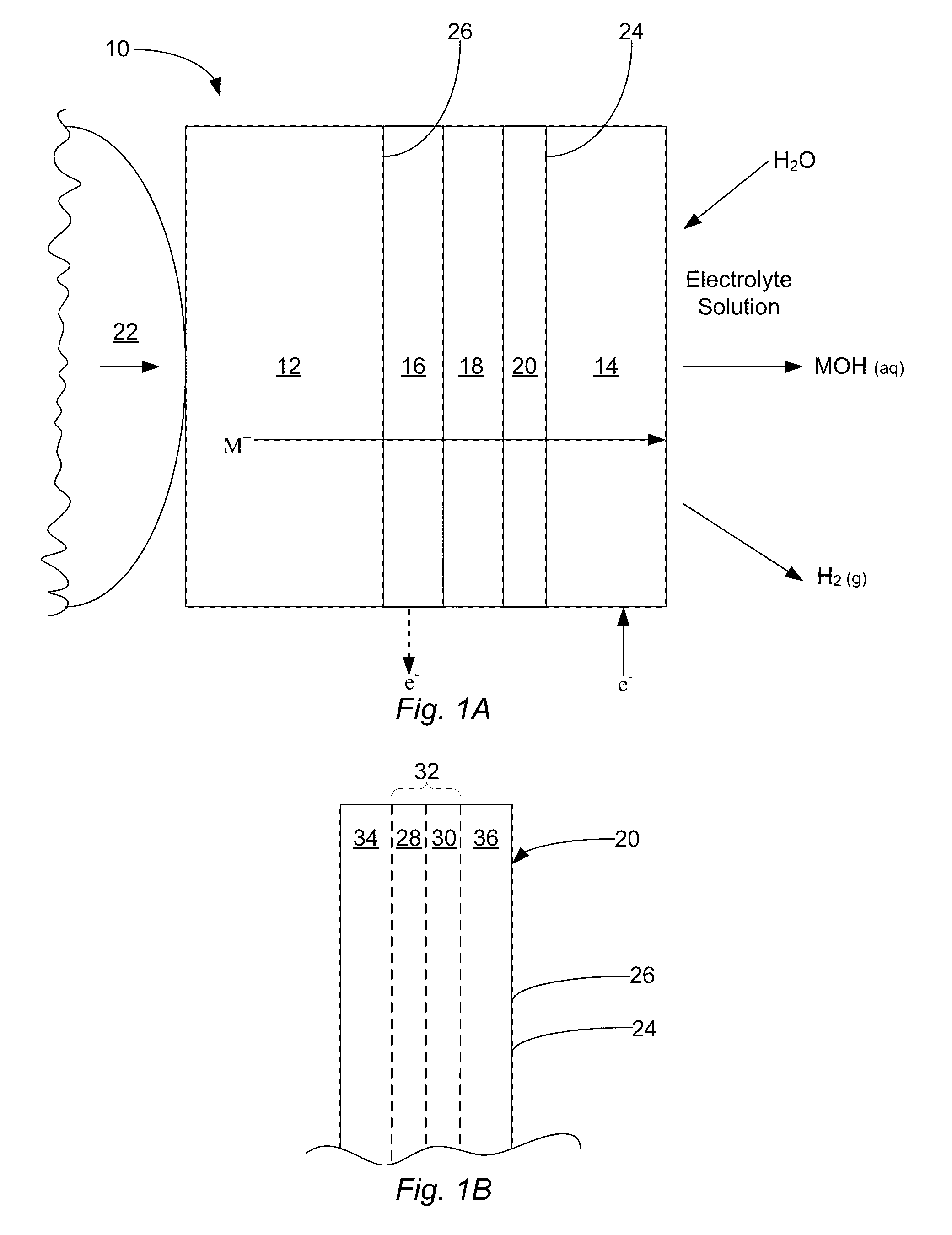
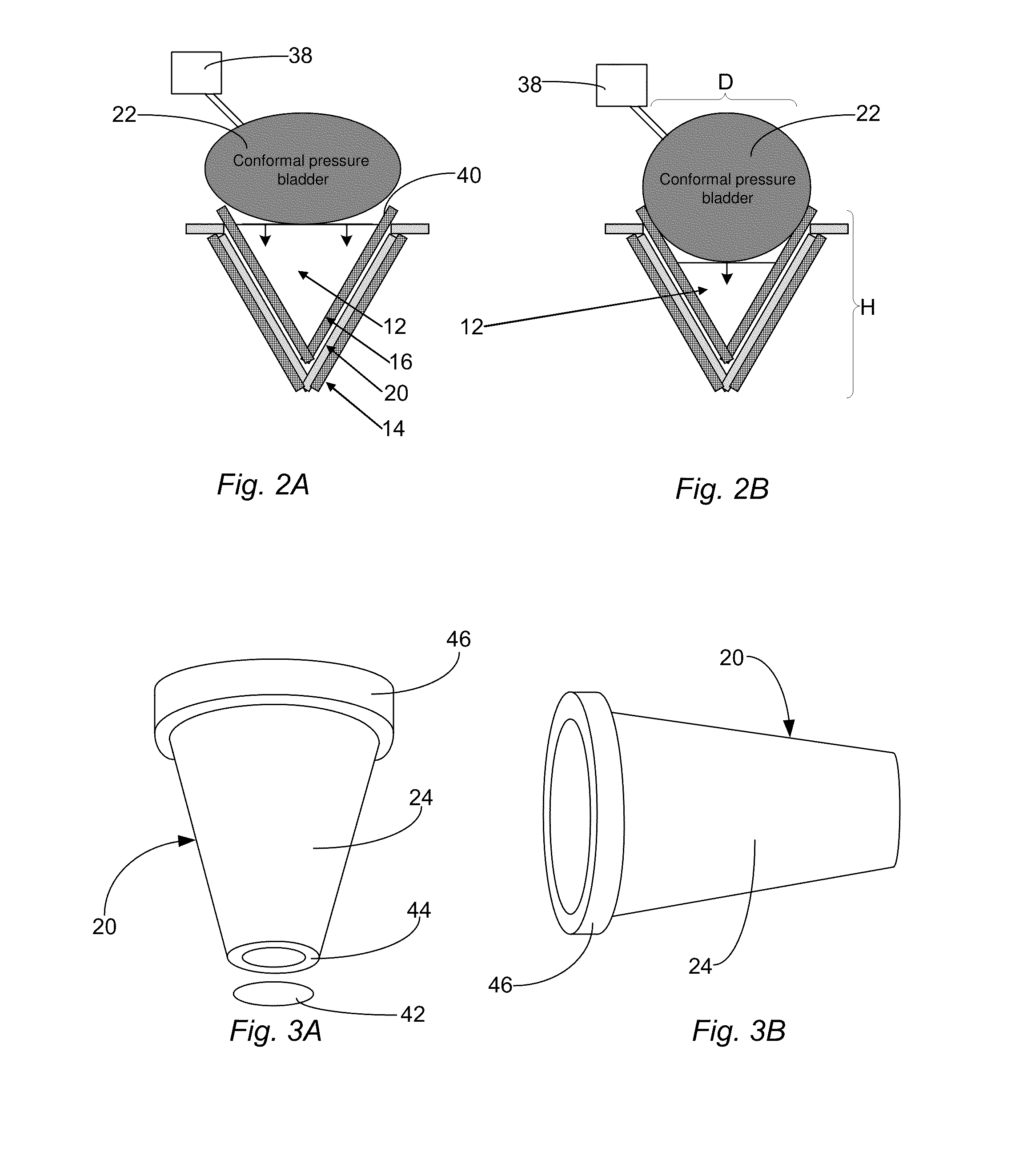
[0014]Although the cell can comprise any suitable shape, in some implementations, the ion-conductive membrane comprises a hollow, three-dimensional conical, hemispherically domed, or pyramidal structure having an interior and an exterior surface. This hollow, three-dimensional structure may pro

Problems solved by technology

As this oxidation process occurs, the

Method used


Image

  • Alkali metal seawater battery
  • Alkali metal seawater battery
  • Alkali metal seawater battery

Examples


Example

Example 1

[0074]In a first example, 2 galvanic cells were prepared according to the described methods. While each cell was substantially identical, a first cell comprised a lithium anode and a LiSICON membrane while a second cell comprised a sodium anode and a NaSICON membrane. Both cells were placed in a 4% sodium chloride aqueous solution in which the pressure of oxygen was not specifically controlled. In this example, the current density of the first and second cells was then plotted against cells' voltage, as shown in FIGS. 6A and 6B, respectively. Specifically, FIG. 6A illustrates that the voltage of the first cell containing a Li anode was measured to be between about 2.5 and about 3 volts. Additionally, FIG. 6B illustrates that the voltage of the second cell containing a Na anode was measured to be between about 2 and about 2.5 volts. Accordingly, this example, shows that, in at least some embodiments, the lithium cell may produce a higher voltage where the cell comprises a li...

Example

Example 2

[0075]In a second example, FIG. 6C contains a graph in which the cell voltage of two cells are plotted against the cells' current density. While the cells used for this graph are substantially similar, the first cell comprises a LiSICON membrane (45B) while the second cell comprises a glass ceramic membrane (GC). Despite the cells' similarities, FIG. 6C shows that the first cell with the LiSICON membrane (45B) produced a higher voltage than did the second cell, which had the glass ceramic membrane (GC). While this difference in cell voltage may be due to a variety of factors, it is theorized that the first cell's increased voltage is a result of its LiSICON membrane having a lower interfacial resistivity than the glass ceramic membrane in the second cell.

Example

Example 3

[0076]In a third example, FIG. 7 illustrates a graph depicting estimated specific energies of different sizes of the described cell as a function of the cells' membrane cone height and diameter. In this example, the weights used for the calculations included the weights of a lithium anode, the current collectors, and a 300 micron thick membrane. Based on the estimates shown in FIG. 7, that figure shows that, in some embodiments, the cone height is preferably greater than about 4 cm and that the specific energy of the cells may also increase with the cones' diameters.


PUM


Abstract

A galvanic cell is disclosed. Generally, the cell includes an alkali metal anode, which electrochemcially oxidizes to release alkali metal ions, and a cathode, which is configured to be exposed to an electrolyte solution. A water-impermeable, alkali-ion-conductive ceramic membrane separates the anode from the cathode. Moreover, an alkali-ion-permeable anode current collector is placed in electrical communication with the anode. In some cases, to keep the anode in contact with the current collector as the cell functions and as the anode is depleted, the cell includes a biasing member that urges the anode against the current collector. To produce electricity, the galvanic cell is exposed to an aqueous electrolyte solution, such as seawater, brine, saltwater, etc.

Description

CROSS-REFERENCE TO RELATED APPLICATIONS[0001]This application claims the benefit of U.S. Provisional Application No. 61 / 096,605, filed Sep. 12, 2008, entitled “Li-Seawater Battery Using Lithium Conductive Membranes,” the entire disclosure of which is hereby incorporated by reference.FIELD OF THE INVENTION[0002]The present invention relates in general to batteries. More particularly, the present invention provides a galvanic cell that comprises an alkali metal anode, an alkali-ion-conductive membrane, and a cathode. To produce electricity, the cathode is exposed to an aqueous electrolyte solution, such as seawater.BACKGROUND OF THE INVENTION[0003]Batteries are known mechanisms that are used to store and release electrical energy for a variety of uses. In order to produce electricity, batteries typically change chemical energy directly into electrical energy. Generally, a single battery includes one or more galvanic cells, wherein each cell is made of 2 half-cells that are electronica...

Claims


Application Information

Patent Timeline
IPC IPC(8): H01M6/16H01M4/58
CPCH01M4/06Y02E60/50H01M4/381H01M4/382H01M4/40H01M4/405H01M4/8605H01M4/885H01M4/90H01M4/921H01M12/04H01M2300/0068H01M2300/0082H01M2300/0094H01M4/38Y02P70/50
Inventor GORDON, JOHN HOWARD
Owner FIELD UPGRADING USA INC
Why Eureka
Try Eureka