Hydrogen production method

a hydrogen production and hydrogen technology, applied in the direction of combustible gas production, combustible gas catalytic treatment, chemistry apparatus and processes, etc., can solve the problems of lower process efficiency and increase in environmental impact, and achieve the effect of maximizing hydrogen production, less utilization of these gases, and constant steam flow ra

Active Publication Date: 2010-03-25
PRAXAIR TECH INC
View PDF2 Cites 22 Cited by
  • Summary
  • Abstract
  • Description
  • Claims
  • Application Information

AI Technical Summary

Benefits of technology

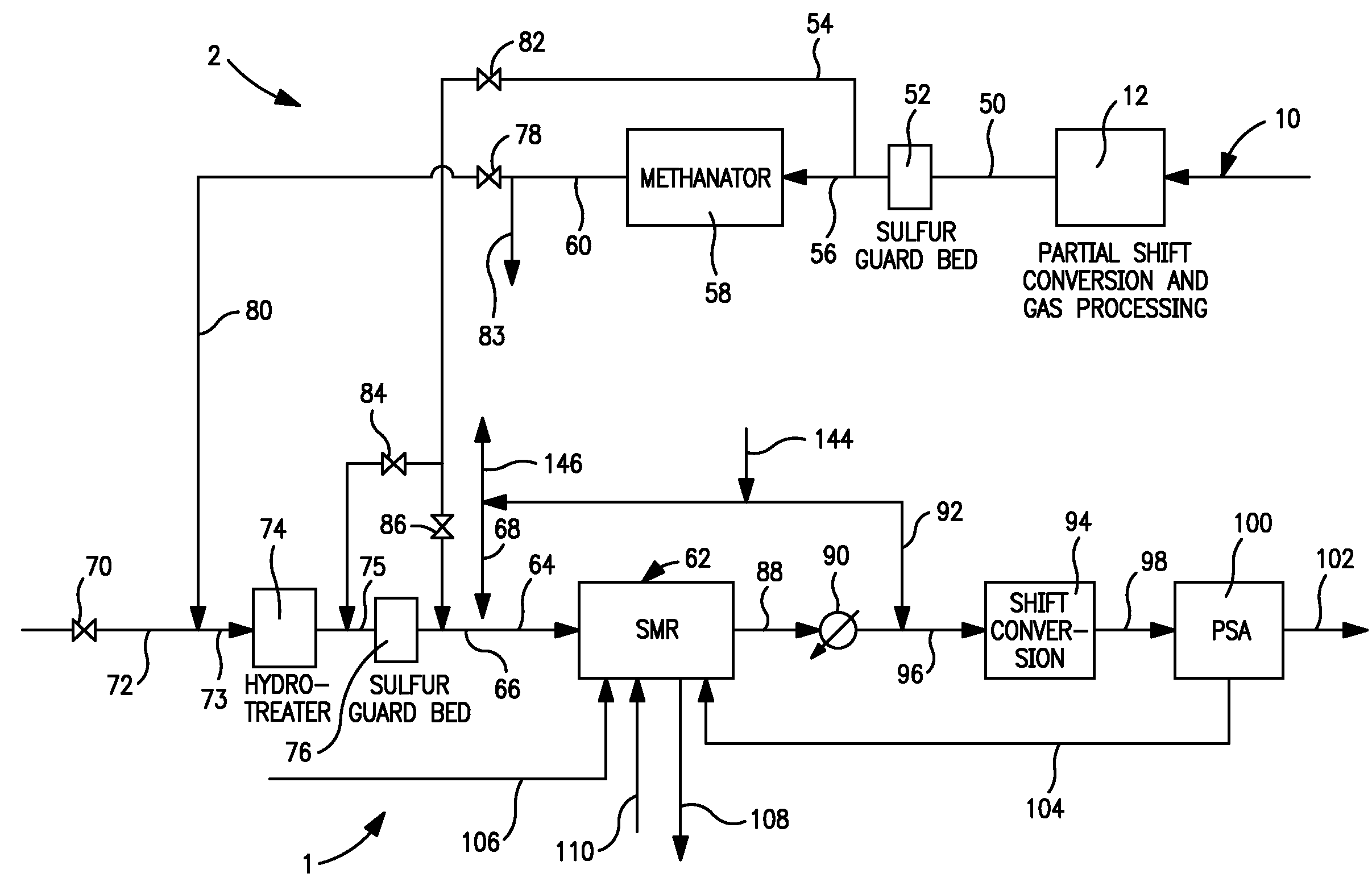
[0014]It is appropriate here to point out, that by maintaining the reformer exit temperature at the reactant side, in other words, the temperature of the intermediate product stream upon directly leaving reformer tubes essentially constant, methane slip is controlled to maximize hydrogen production. The maintenance of the flue gas side temperature essentially constant, or in other words, the flue gas temperature before reaching the convective section of the steam methane reformer essentially constant, coupled with the maintenance of the flue gas flow rate essentially constant, the amount of steam generated in the convective section of the steam methane reformer can be maintained at an essentially constant flow rate. And be maintaining the steam flow rate essentially constant, the steam to carbon ratio will increase with the use of the hydrogen and carbon monoxide containing stream in the second feed stream to allow the increased carbon monoxide content of the feed to be subjected to the water gas shift reaction to an increased extent within the steam methane reformer and to provide steam to the water gas shift reaction occurring in the shift conversion unit used in the processing of the intermediate product stream. The end result of such control is to allow the same amount of hydrogen to be produced when the feed to the steam methane reformer is switched to the second feed stream.
[0015]As is apparent from the above description, the use of part of the synthesis gas to form a hydrogen and carbon monoxide containing stream that can serve as part of the feed to a steam methane reformer has the obvious advantage of not using the same amount of natural gas or synthetic natural gas or refinery off-gas in the production of the hydrogen. As a result, there can be less utilization of these gases to not only produce a cost savings but to allow the synthetic natural gas to be available for sale. A yet further savings is brought about due to the fact that the carbon monoxide content of the feed to the steam methane reformer when synthesis gas is used will allow the exothermic water gas shift reaction to occur at a greater extent. The heat produced by such reaction as well as the reduction in hydrocarbon feed rate to the reformer will reduce the amount of fuel that would otherwise be required to fire burners utilized within the furnace section of the steam methane reformer. Such fuel is provided by part of the feed to be reacted that can contain natural gas refinery off-gas, naphtha or synthetic natural gas and combinations thereof.
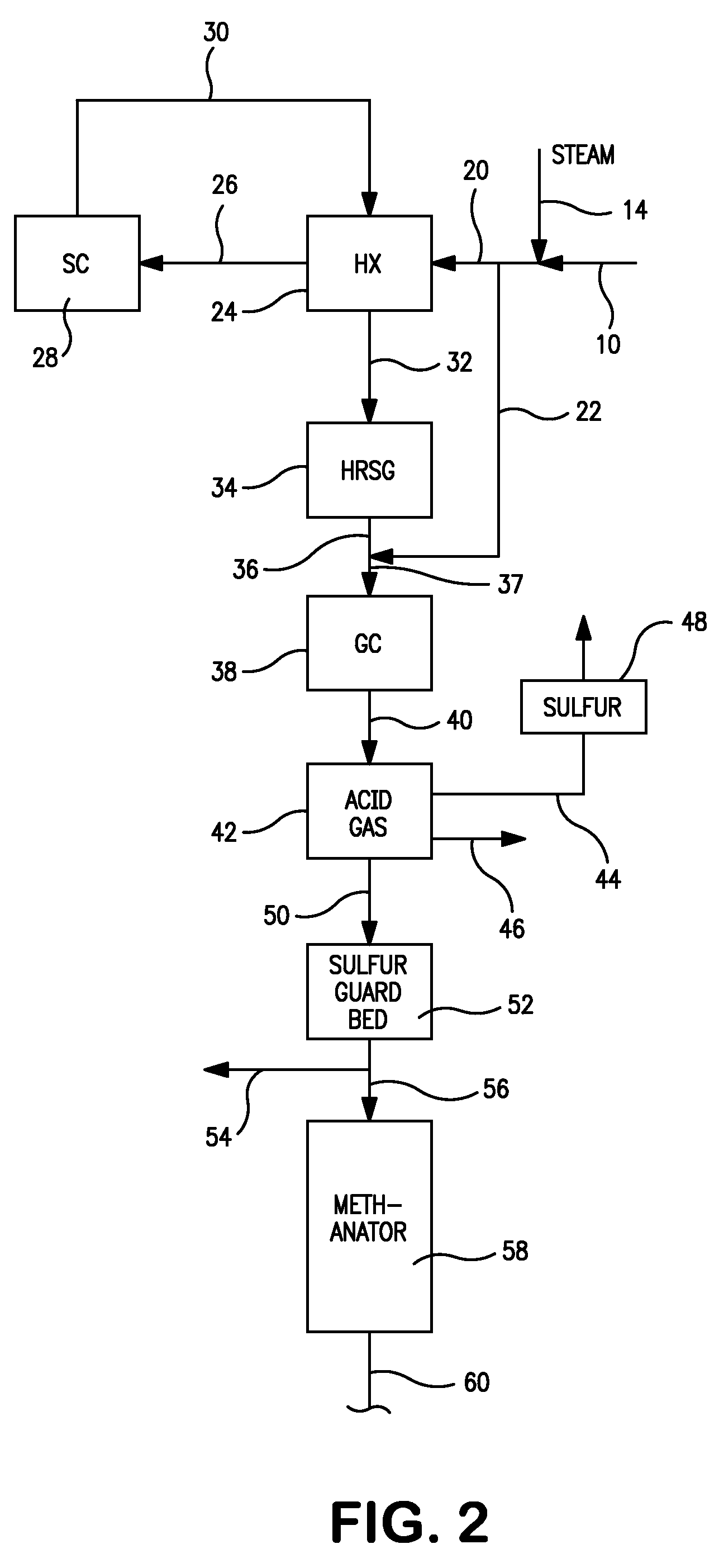
[0016]Additionally, as mentioned above, the present invention allows for certain economic advantages to be realized in the construction of the gasification facility 2 and for the hydrogen to be supplied on a more reliable basis. If hydrogen production were to be made part of the gasification project, then the gasification facility would require a second shift conversion and a pressure swing adsorption unit as well as associated heat exchangers, piping and etc. Although the use of a hydrogen and carbon monoxide containing stream from a unit designed to produce hydrogen is contemplated by the present invention, the present invention certainly allows for a simplified and less expensive gasification train within the gasification facility. Additionally, a gasifier has between about a 85 percent and about 90 percent on stream factor while a steam methane reformer has about a 98 percent on-stream factor. The steam methane reformer can be switched between the two types of feed streams thereby increasing the reliability of the hydrogen supply. This is important where a steam methane forming facility exists and the gasifiers are being built at a later time. Other advantages will become apparent from the discussion that will follow below.

Problems solved by technology

From the simulations, it was concluded that the environmental impact increases in terms of higher carbon dioxide emissions and lower process efficiency as the feed stock becomes heavier.

Method used


Image

  • Hydrogen production method
  • Hydrogen production method
  • Hydrogen production method

Examples


case 7

[0061 generates maximum amount of steam because of the high amount of carbon dioxide in the synthesis gas feed that needs to be heated in the furnace section of the steam methane reformer and cooled subsequently. The seventh row shows the net energy consumption. Case 8 where the synthesis gas is taken after the carbon dioxide removal has the least energy consumption. All three cases have the same steam to carbon ratio when calculated without counting carbon monoxide as carbon. The ninth row shows the steam to carbon ratio when carbon monoxide is included in the carbon count. Case 1 has the least steam to carbon ratio as it has the highest carbon monoxide content in the synthesis gas fed to the steam methane reformer. The tenth row shows the oxygen content in the flue gas on a dry basis. The reformer absorbed duty is shown next. Case 7 has the highest duty among the three cases as this case has a high carbon dioxide content in the synthesis gas fed to the steam methane reformer that ...


PUM

PropertyMeasurementUnit
molar ratioaaaaaaaaaa
exit temperatureaaaaaaaaaa

Abstract

A method of producing a hydrogen product stream in which a steam stream is reacted with a hydrocarbon containing stream within a steam methane reformer. The resulting product stream is subjected to a water gas shift reaction and then to pressure swing adsorption to produce the hydrogen product stream. The hydrocarbon stream is alternatively formed from a first type of feed stream made up of natural gas, refinery off-gas, naphtha or synthetic natural gas or combinations thereof and a second type that is additionally made up of a hydrogen and carbon monoxide containing gas. During use of both of the types of feed streams, the flow rate of the steam stream is not substantially changed and reformer exit temperatures of both the reactant and the flue gas side are held essentially constant.

Description

FIELD OF THE INVENTION [0001]The present invention relates to a method for producing hydrogen in which a hydrocarbon containing stream is reacted with steam in a steam methane reformer to produce a hydrogen containing intermediate product stream that is subsequently subjected to a water gas shift reaction to produce additional hydrogen and to pressure swing adsorption to separate the hydrogen and thereby to produce the hydrogen product stream. More particularly, the present invention relates to such a method in which the hydrocarbon stream can be alternatively formed from a methane containing feed or a feed that additionally contains hydrogen and carbon monoxide.BACKGROUND OF THE INVENTION [0002]Hydrogen has many current industrial uses and potential future uses involving the supply of energy in fuel cells. For example, there presently exists a continuing need for hydrogen to treat high sulfur content crude oil in the production of fuels. In the future, hydrogen may be used as an au...

Claims


Application Information

Patent Timeline
Patent Type & Authority Applications(United States)
IPC IPC(8): C01B3/12
CPCC01B3/16C10K3/04C01B3/48C01B2203/0216C01B2203/0233C01B2203/0283C01B2203/0415C01B2203/043C01B2203/044C01B2203/0445C01B2203/0455C01B2203/0475C01B2203/0485C01B2203/0495C01B2203/06C01B2203/0894C01B2203/1258C01B2203/147C01B2203/148C01B2203/84C10G2/30C10G67/06C10J3/00C10J2300/1662C10J2300/1884C10K1/004C10K1/32C01B3/384
Inventor DRNEVICH, RAYMOND FRANCISWATWE, RAMCHANDRA M.
Owner PRAXAIR TECH INC
Why Eureka
Try Eureka