Pollution control system

a pollution control and pollution technology, applied in the field of pollution control systems, can solve the problems of harmful to the engine crankcase, inability to completely seal off the piston cylinder, and inability to vent the gases to the atmosphere, so as to reduce the vacuum pressure of the engine, reduce the production of blowby gases, and reduce the fluid flow rate

Active Publication Date: 2010-03-25
SVMTECH
View PDF9 Cites 53 Cited by
  • Summary
  • Abstract
  • Description
  • Claims
  • Application Information

AI Technical Summary

Benefits of technology

[0015]The pollution control system further includes a PCV valve having an inlet and an outlet adapted to vent blow-by gas out from a combustion engine. Preferably, the PCV valve is a two-stage check valve. A fluid regulator associated with the PCV valve and responsive to the controller is used in the pollution control system to selectively modulate engine vacuum pressure to adjustably increase or decrease the fluid flow rate of blow-by gas venting from the combustion engine. The controller adjustably positions the fluid regulator to vary the degree of engine vacuum based, in part, on measurements taken from one or more of the aforementioned sensors. In a preferred embodiment, the PCV valve inlet connects to a crankcase and the PCV valve outlet connects to an intake manifold of an internal combustion engine. The controller decreases the engine vacuum pressure during periods of decreased blow-by gas production in the internal combustion engine, thereby decreasing the fluid flow rate through the PCV valve, and increases the engine vacuum pressure during periods of increased blow-by gas production in the internal combustion engine, thereby increasing the fluid flow rate through the PCV valve.

Problems solved by technology

Unfortunately, the piston rings are unable to completely seal off the piston cylinder.
Blow-by gases mainly consist of contaminants such as hydrocarbons (unburned fuel), carbon dioxide or water vapor, all of which are harmful to the engine crankcase.
Simply venting these gases to the atmosphere increases air pollution.
Condensed contaminants form corrosive acids and sludge in the interior of the crankcase that dilutes the lubricating oil.
This decreases the ability of the oil to lubricate the cylinder and crankshaft.
Degraded oil that fails to properly lubricate the crankcase components (e.g. the crankshaft and connecting rods) can be a factor in poor engine performance.
Inadequate crankcase lubrication contributes to unnecessary wear on the piston rings which simultaneously reduces the quality of the seal between the combustion chamber and the crankcase.
As the engine ages, the gaps between the piston rings and cylinder walls increase resulting in larger quantities of blow-by gases entering the crankcase.
Too much blow-by gases entering the crankcase can cause power loss and even engine failure.
Moreover, condensed water in the blow-by gases can cause engine parts to rust.
One-way check valve-based PCV valves are unable to account for changes in the quantity of blow-by gases that exist in the crankcase at any given time.
Hence, such an improved PCV valve that solely relies on engine vacuum and a spring-biased restrictor does not optimize the ventilation of blow-by gases from the crankcase to the intake manifold, especially in situations where the vehicle is constantly changing speeds (e.g. city driving or stop and go highway traffic).
But, a spring-based PCV valve is unable to account for the difference in blow-by gas production between 2,500 rpm and 900 rpm because the spring-based PCV valve experiences a similar pressure differential between the intake manifold and the crankcase at these different engine speeds.
As the vehicle accelerates, blow-by gas production increases, but the engine vacuum decreases due to the increased engine load.
Thus, the spring-based PCV valve may vent an inadequate quantity of blow-by gases from the crankcase during acceleration.
Such a spring-based PCV valve system is incapable of venting blow-by gases based on blow-by gas production because the spring is only responsive to engine vacuum.
But, blow-by gas production is not based solely on vacuum pressure, throttle position, or a combination.
Hence, the Collin's PCV valve also inadequately vents blow-by gases from the crankcase to the intake manifold when the engine load varies at similar throttle positions.
Failure to change the lubricating oil at adequate intervals (typically every 3,000 to 6,000 miles) can lead to a PCV valve system contaminated with sludge.
A plugged PCV valve system will eventually damage the engine.
OBD originally illuminated a malfunction indicator light (MIL) for a detected problem, but did not provide information regarding the nature of the problem.
Unfortunately, OBD-I did not succeed at the time as the infrastructure for testing and reporting emissions-specific diagnostic information was not standardized or widely accepted.
Technical difficulties in obtaining standardized and reliable emission information from all vehicles led to an inability to effectively implement an annual testing program.

Method used


Image

  • Pollution control system
  • Pollution control system
  • Pollution control system

Examples


Embodiment Construction

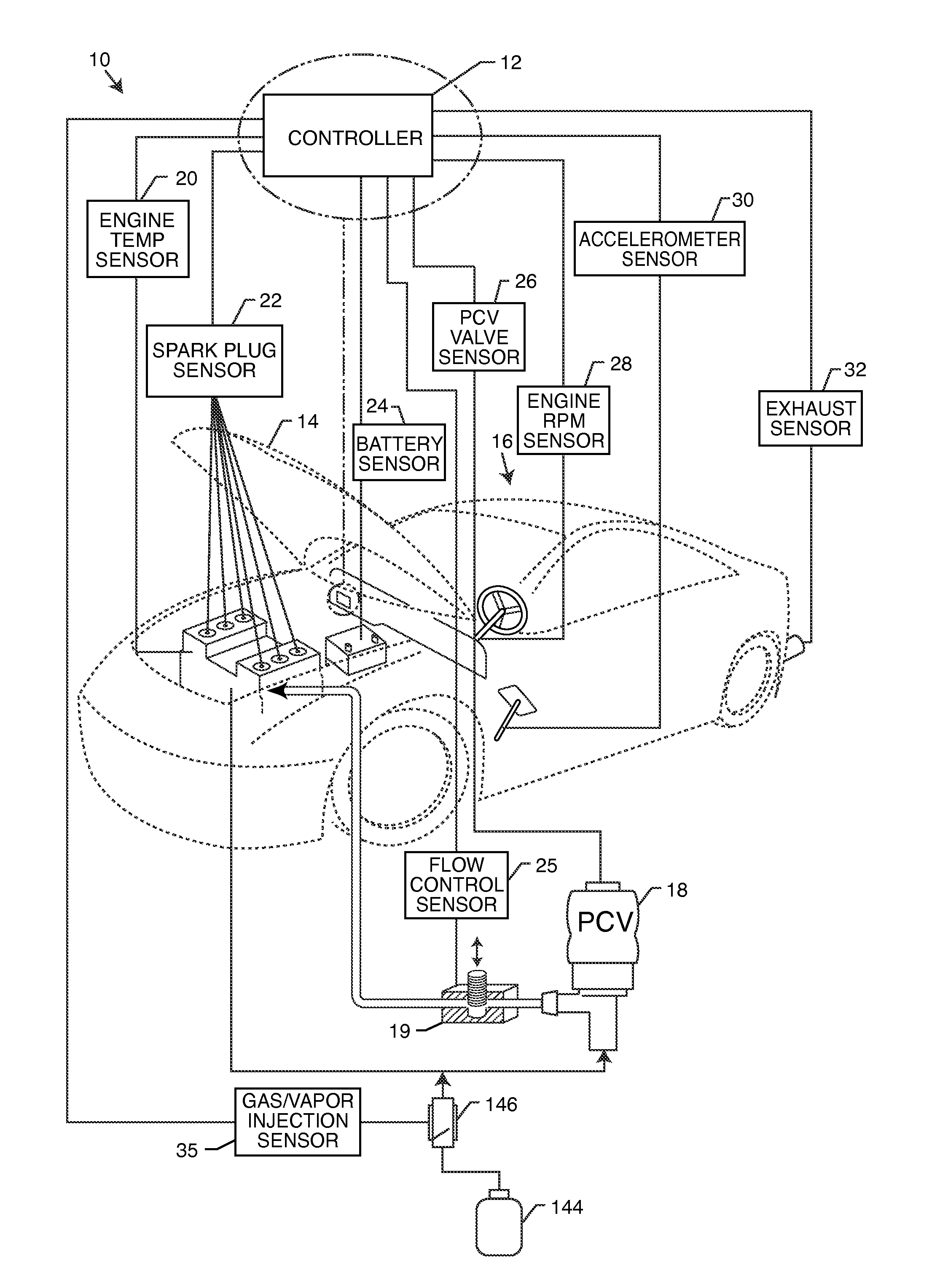
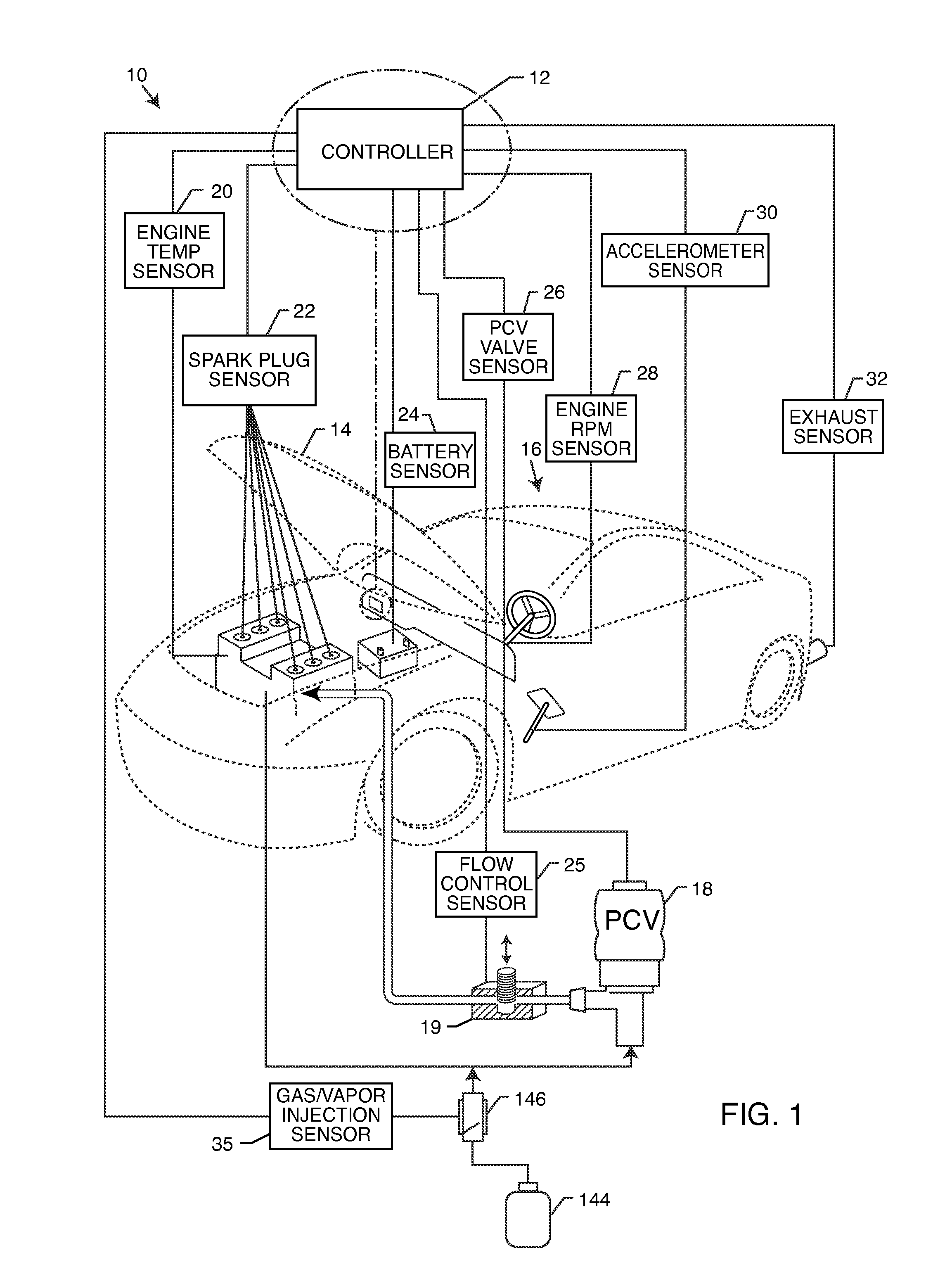
[0029]As shown in the drawings for purposes of illustration, the present invention for a pollution control system is referred to generally by the reference number 10. In FIG. 1, the pollution control system 10 is generally illustrated as having a controller 12 preferably mounted under a hood 14 of an automobile 16. The controller 12 is electrically coupled to any one of a plurality of sensors that monitor and measure the real-time operating conditions and performance of the automobile 16. The controller 12 regulates the flow rate of blow-by gases by regulating the engine vacuum in a combustion engine through digital control of a PCV valve 18 and a flow control orifice 19. The controller 12 receives real-time input from sensors that might include an engine temperature sensor 20, a spark plug sensor 22, a battery sensor 24, a flow control sensor 25, a PCV valve sensor 26, an engine RPM sensor 28, an accelerometer sensor 30, an exhaust sensor 32, and a gas / vapor injection sensor 33. Da...


PUM


Abstract

The pollution control system includes a controller coupled to a sensor monitoring an operational characteristic of a combustion engine, such as engine RPM. A PCV valve having an inlet and an outlet is adapted to vent blow-by gas out from the combustion engine. A fluid regulator associated with the PCV valve and responsive to the controller selectively modulates engine vacuum pressure to adjustably increase or decrease a fluid flow rate of blow-by gas venting from the combustion engine. The controller selectively adjustably positions the fluid regulator to vary the degree of vacuum pressure to optimize the recycling of blow-by gases.

Description

BACKGROUND OF THE INVENTION[0001]The present invention generally relates to a system for controlling pollution. More particularly, the present invention relates to a system that systematically controls a PCV valve assembly that recycles engine fuel by-products, reduces emissions and improves engine performance.[0002]The basic operation of standard internal combustion (IC) engines vary somewhat based on the type of combustion process, the quantity of cylinders and the desired use / functionality. For instance, in a traditional two-stroke engine, oil is pre-mixed with fuel and air before entry into the crankcase. The oil / fuel / air mixture is drawn into the crankcase by a vacuum created by the piston during intake. The oil / fuel mixture provides lubrication for the cylinder walls, crankshaft and connecting rod bearings in the crankcase. The fuel is then compressed and ignited by a spark plug that causes the fuel to burn. The piston is then pushed downwardly and the exhaust fumes are allowe...

Claims


Application Information

Patent Timeline
Patent Type & Authority Applications(United States)
IPC IPC(8): G06F19/00F02B25/06F02B43/08
CPCF01M13/00F01M13/0011F01M2013/0005F01M2013/0022Y02T10/36Y02T10/121F02D19/0681F02D19/0644F02D19/0647F02M25/06Y02T10/30F01M13/04F01M13/02Y02T10/12
Inventor MONROS, SERGE V.
Owner SVMTECH
Why Eureka
Try Eureka