Multiple Bioactive Agent Eluting Stents

a bioactive agent and elution stent technology, applied in the field of applicative and method of multiple bioactive agent elution, can solve the problems of significant re-narrowing of treated vessels, vessel “scarring”, blood clot formation, etc., and achieve the effect of reducing the elution ra

Inactive Publication Date: 2010-04-15
MEDTRONIC VASCULAR INC
View PDF7 Cites 5 Cited by
  • Summary
  • Abstract
  • Description
  • Claims
  • Application Information

AI Technical Summary

Benefits of technology

[0014]In another embodiment, the one or more of the at least two bioactive agents increases the elution rate of one or more of the other of the at least two bioactive agents. Alternatively, the one or more of the at least two bioactive agents decreases the elution rate of one or more of the other of the at least two bioactive agents.

Problems solved by technology

Soon after the procedure, however, a significant proportion of treated vessels re-narrow.
The natural antithrombogenic lining of the vessel lumen may become damaged thereby exposing thrombogenic cellular components, such as matrix proteins.
The cellular components, along with the generally antithrombogenic nature of any implanted materials (e.g., a stent), may lead to the formation of a thrombus, or blood clot.
This exuberant cellular growth may lead to vessel “scarring” and significant restenosis.
Some antithrombogenic agents, however, may not be effective against intimal hyperplasia.
For example, when the vessel wall cannot easily absorb a bioactive agent it would not be desirable to have a fast elution rate because the eluted bioactive agent will not be incorporated into the vessel wall.
However, this may cause unwanted systemic dissemination of a bioactive agent which may be an inherently toxic substance such as paclitaxel.

Method used


Image

  • Multiple Bioactive Agent Eluting Stents
  • Multiple Bioactive Agent Eluting Stents
  • Multiple Bioactive Agent Eluting Stents

Examples


example 1

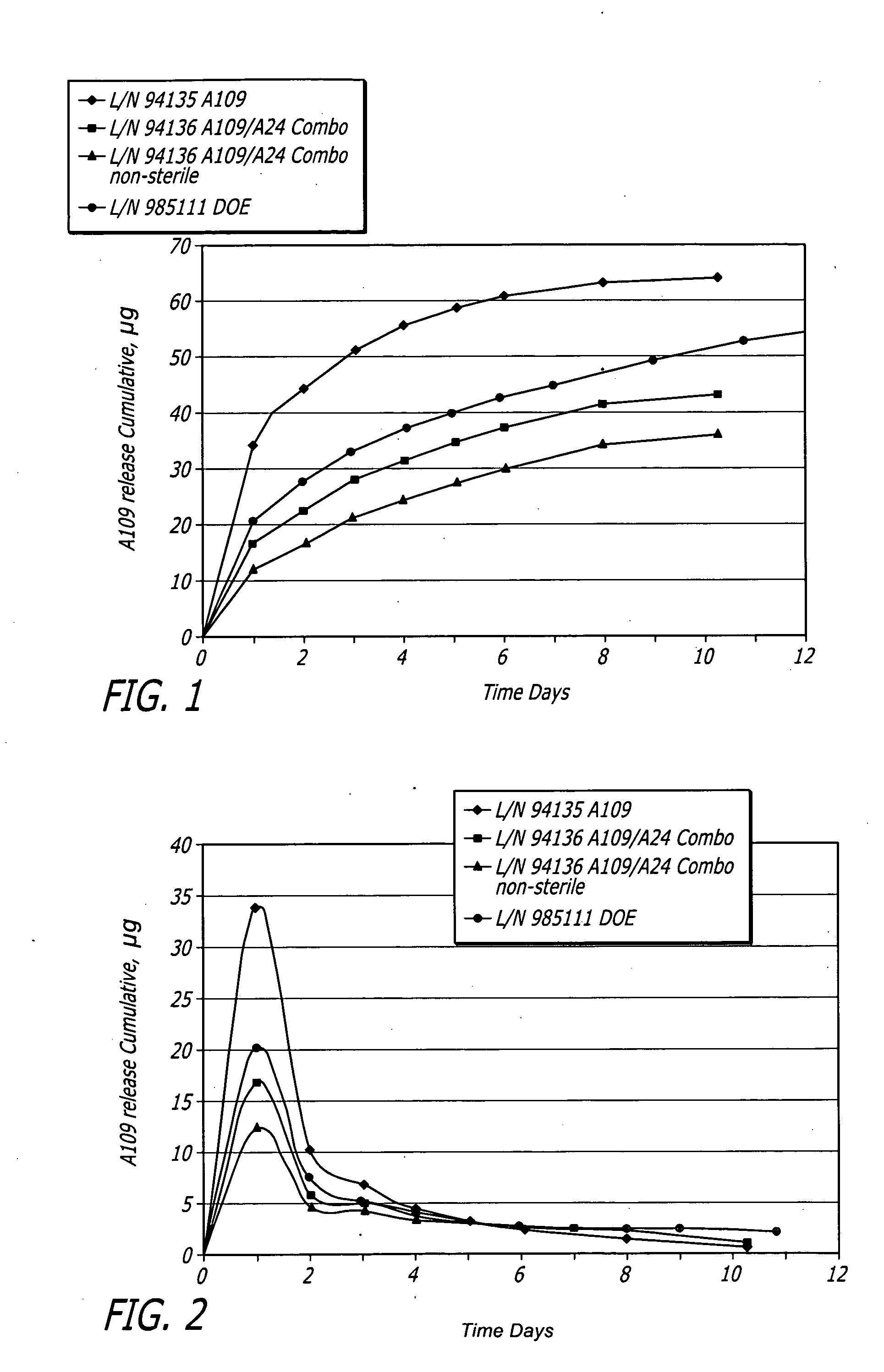
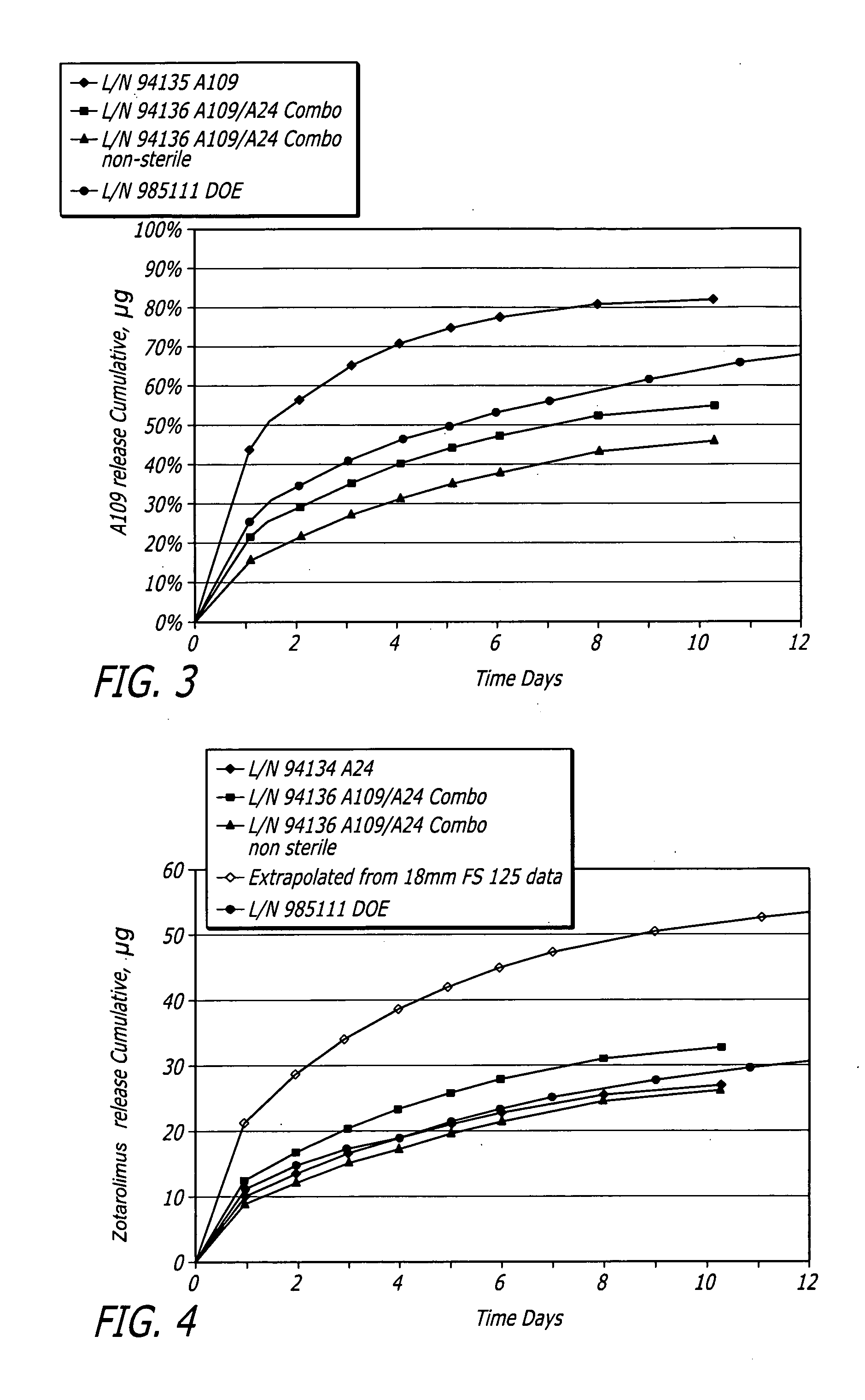
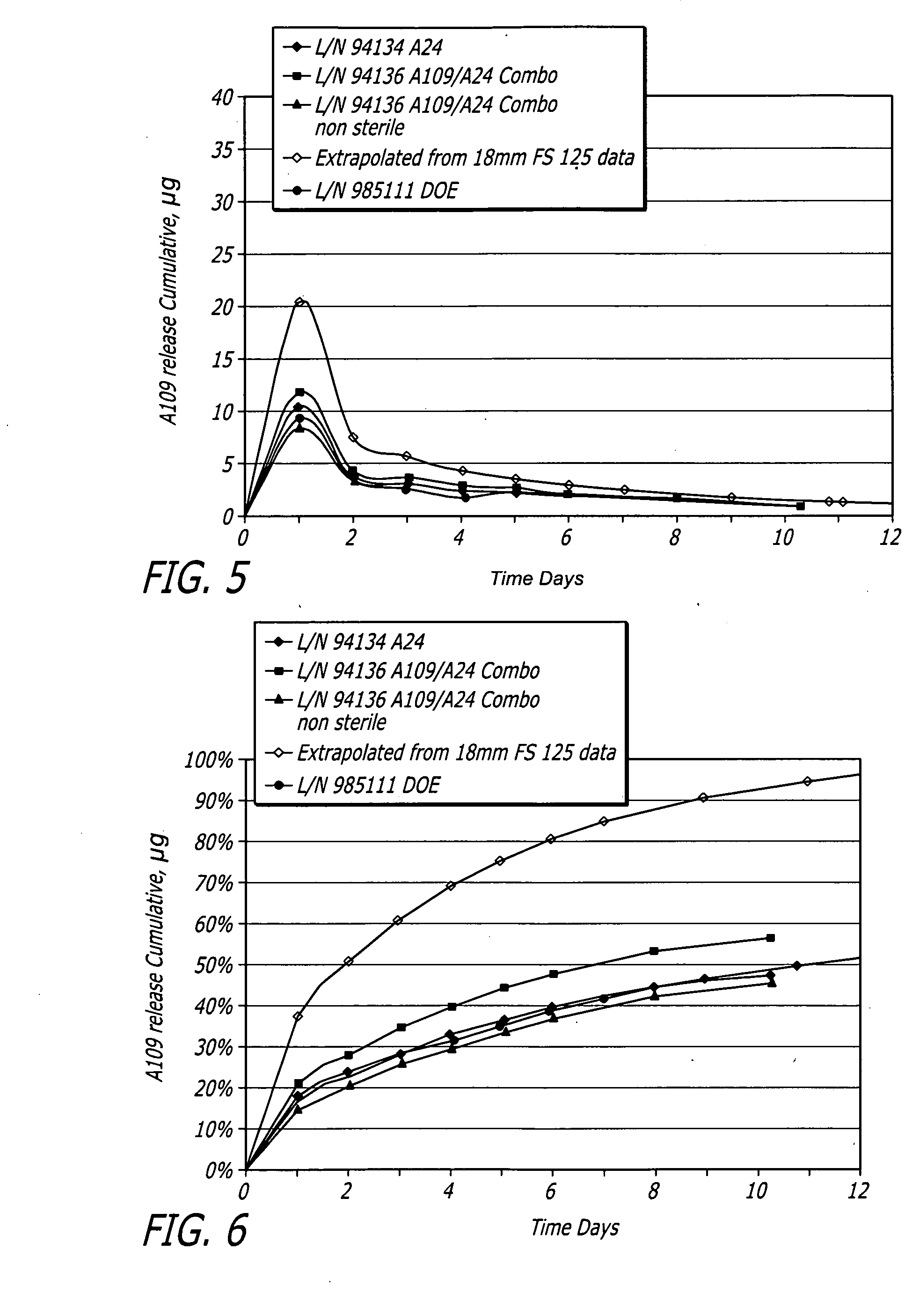
[0063]12 mm parylene coated stents were used for all builds. Stents were loaded onto 3.0 RX catheters. Formulation shelf life for arms containing fluocinolone (Groups A and B) was limited to 24 hours maximum. Groups C and D had a formulation shelf-life of 72 hrs. Groups A, C and D were dried in vacuum oven at 25° C. and Group B was dried in a class IIB2 laminar flow hood. All groups were dried for a minimum of 12 hours. All groups were EtO (ethylene oxide) sterilized. These bioactive agents were treated as light sensitive. During the spray process, the solution was vortexed prior to filling syringe. No more than 3 ml of solution was added to the syringe during each refill.

TABLE 1Build ParametersTargetFluocinoloneDryWetBioactiveTargetCoatingCoatingagent LoadZotarolimusC10:C19:PVPWeightWeightGroup(μg)Load (μg)Ratio(μg)(μg)DryingSterilizationSolventA0038:57:5466 + / − 47466 + / − 23VacuumEtODichloroOvenmethaneB06038:57:5466 + / − 47466 + / − 23IIB2(DCM)C80038:57:5466 + / − 47466 + / − 23VacuumOven...

example 2

[0073]Medium vessel 3.5×18 mm Driver® stents with a combination of fluocinolone and zotarolimus bioactive agents and C10:C19:PVP polymers (38:57:5) were coated for development of different coating variations.

[0074]Stents were coated with a combination of fluocinolone and / or zotarolimus. Group 1 served as a control for 18 mm stent presently tested. Group 2 used the same formulation but with stents pre-crimped to provide preferential outer diameter (OD) coating. Groups 3 to 5 each investigated different layered approaches. Each design maintained the same total amount of each bioactive agent. In Group 3, the bioactive agents were loaded only into the base layer, with a polymer cap coat of equal thickness above. A question to be answered was whether this layering may slow and extend the elution of both bioactive agents, and show whether the cap coat serves as intended or whether the base coat re-solvates and becomes homogeneous throughout. In Groups 4 and 5, the bioactive agents were sp...


PUM

PropertyMeasurementUnit
timeaaaaaaaaaa
bioactiveaaaaaaaaaa
hydrophobicityaaaaaaaaaa

Abstract

The apparatus and methods of the present invention in a broad aspect provide novel multiple bioactive agent eluting stents for treating vascular diseases and conditions. Controlled elution of bioactive agents is achieved by the presence of the bioactive agents themselves. One or more characteristics of the bioactive agents cause variations in elution rates or profiles or the other bioactive agents.

Description

FIELD OF THE INVENTION[0001]The present disclosure relates to apparatus and methods for multiple bioactive agent controlled elution useful for treating, for example, vascular diseases and conditions.BACKGROUND OF THE INVENTION[0002]Stents are generally cylindrical shaped devices which are radially expandable to hold open a segment of a vessel or other anatomical lumen after implantation into the body lumen. Stents have been developed with coatings to deliver bioactive agents or other therapeutic agents. Various types of stents are in use, including expandable and self-expanding stents. Expandable stents generally are conveyed to the area to be treated on balloon catheters or other expandable devices. For insertion, the stent is positioned in a compressed configuration along the delivery device, for example, crimped onto a balloon that is folded or otherwise wrapped about a guide wire that is part of the delivery device. After the stent is positioned across the lesion, it is expanded...

Claims


Application Information

Patent Timeline
Patent Type & Authority Applications(United States)
IPC IPC(8): A61L27/54A61F2/82
CPCA61L31/10A61L2300/61A61L2300/45A61L31/16
Inventor VASQUEZ, NATIVIDADBILGE, ISKENDER MATTPETERSON, SUSAN REA
Owner MEDTRONIC VASCULAR INC
Why Eureka
Try Eureka