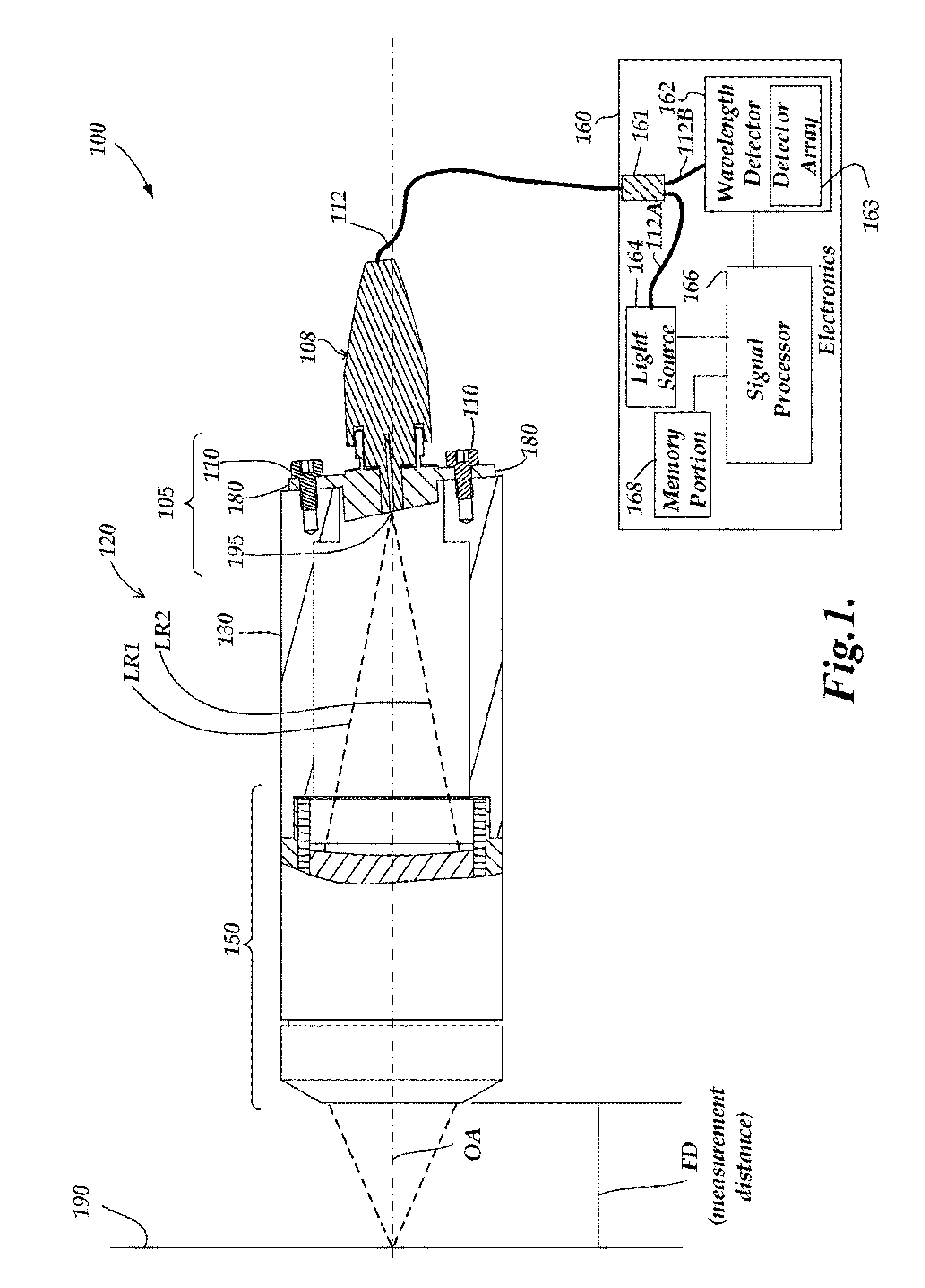
[0007]In accordance with various exemplary embodiments of the present invention, a
high intensity light source configuration is provided, which has a stable, long lifetime. The invention further provides a method of operating such light source configuration. In various exemplary embodiments, a
high intensity light source configuration includes a movable member mounted to a movable member
actuator; at least one light-emitting phosphor region associated with the movable member; an input light source configured to illuminate the light-emitting phosphor region(s) at an illuminated spot that is fixed relative to an emitted light output
coupling region; and a light source controller operably connected to the movable member actuator and the input light source. In operation, the input light source (e.g.,
laser) provides a high-intensity input light to the illuminated spot to thereby cause the light-emitting phosphor region(s) to emit high-intensity output light from an excited phosphor spot or track included in an emitted light output
coupling region. In various embodiments, the emitted light output
coupling region is located
proximate to the illuminated spot. At the same time, with the operation of the movable member actuator, the light-emitting phosphor region(s) continuously moves relative to the illuminated spot so as to reduce optical
quenching of the emission, and
photobleaching of the phosphor region(s), to thereby avoid
quenching from high
photon flux in the emitted light output coupling region and also to extend the life of the phosphor region(s) and hence the overall
operating life of the light source configuration. In various embodiments, the light source can be modulated at a rate equal to or greater than a typical measurement rate of a CPS or other precision measurement instrument.
[0008]In accordance with one aspect of the present invention, a light-emitting phosphor region or unique sub-region associated with the movable member is distributed over an area of at least several times a nominal area of the emitted light output coupling region. In some embodiments and / or applications, it may be advantageous to distribute each light emitting phosphor region and / or sub-region over an area of at least 25 times, or 50 times or more, the area of the excited phosphor spot or track and / or the emitted light output coupling region, in order to extend the life of the light source configuration to a desirable level. In some embodiments suitable for more demanding applications, it may be advantageous to distribute a light emitting phosphor region over an area of at least 100 times, 200 times or even 500 or many more times the area of the emitted light output coupling region, in order to extend the life of the light source configuration to a desirable level.
[0009]In accordance with another aspect of the present invention, in some embodiments, the input light source is configured to provide an average intensity at the illuminated spot of at least 1 milliwatts / mm2 for relatively larger illuminated spots or at least 20 milliwatts / mm2 for smaller illuminated spots, or at least 2000 milliwatts / mm2 for even smaller illuminated spots, which is sufficient to cause the light-emitting phosphor region(s) to emit a level of output light that is useful in some applications. In more demanding applications (e.g., for very short measurement cycles, or the like) it may be advantageous when the input light source is configured to provide an average intensity of at least 200 milliwatts / mm2, 5000 milliwatts / mm2, or even 100 W / mm2 or more at relatively smaller illuminated spots, in order to cause the light-emitting phosphor region(s) to emit a desirable level of high-intensity output light.
[0012]In accordance with another aspect of the present invention, in some embodiments, the illuminated spot may have a nominal spot
diameter of at most 150 microns
proximate to a surface of the light-emitting phosphor region(s), and the associated excited phosphor spot or track may have a
diameter or track width of at most 750 microns, in order to facilitate a compact light source configuration. In other embodiments, it may be advantageous if the illuminated spot has a nominal spot
diameter of at most 100 microns, 50 micron, or even 20 microns or less,
proximate to a surface of the light-emitting phosphor region(s), and the associated excited phosphor spot or track may have a diameter or track width of at most 500 microns, 300 microns, or even 200 microns or less, in order to facilitate an even more compact and / or economical light source configuration. However, these embodiments are exemplary only, and not limiting. In accordance with another aspect of the invention, the light source configuration may include an
optical fiber, and an entrance aperture of the
optical fiber may be located to receive light from the emitted light output coupling region. In accordance with another aspect of the present invention, in some embodiments, the entrance aperture of the
optical fiber may be located at a distance of at most 2.0
millimeter, or 1.0
millimeter, or at most 500 microns, or 300 microns or less, from the excited phosphor spot or track, in order to efficiently receive light in the emitted light output coupling region.
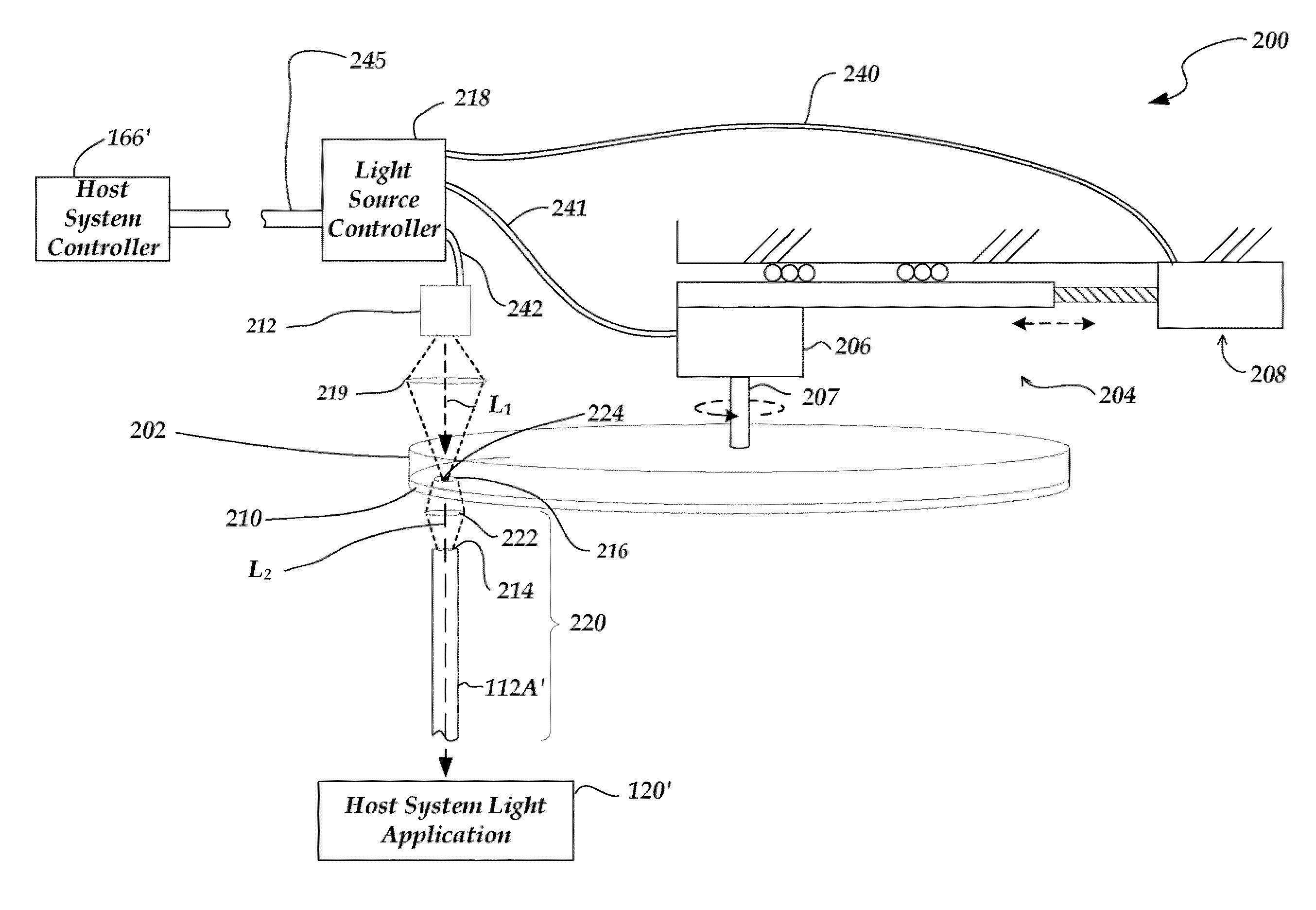
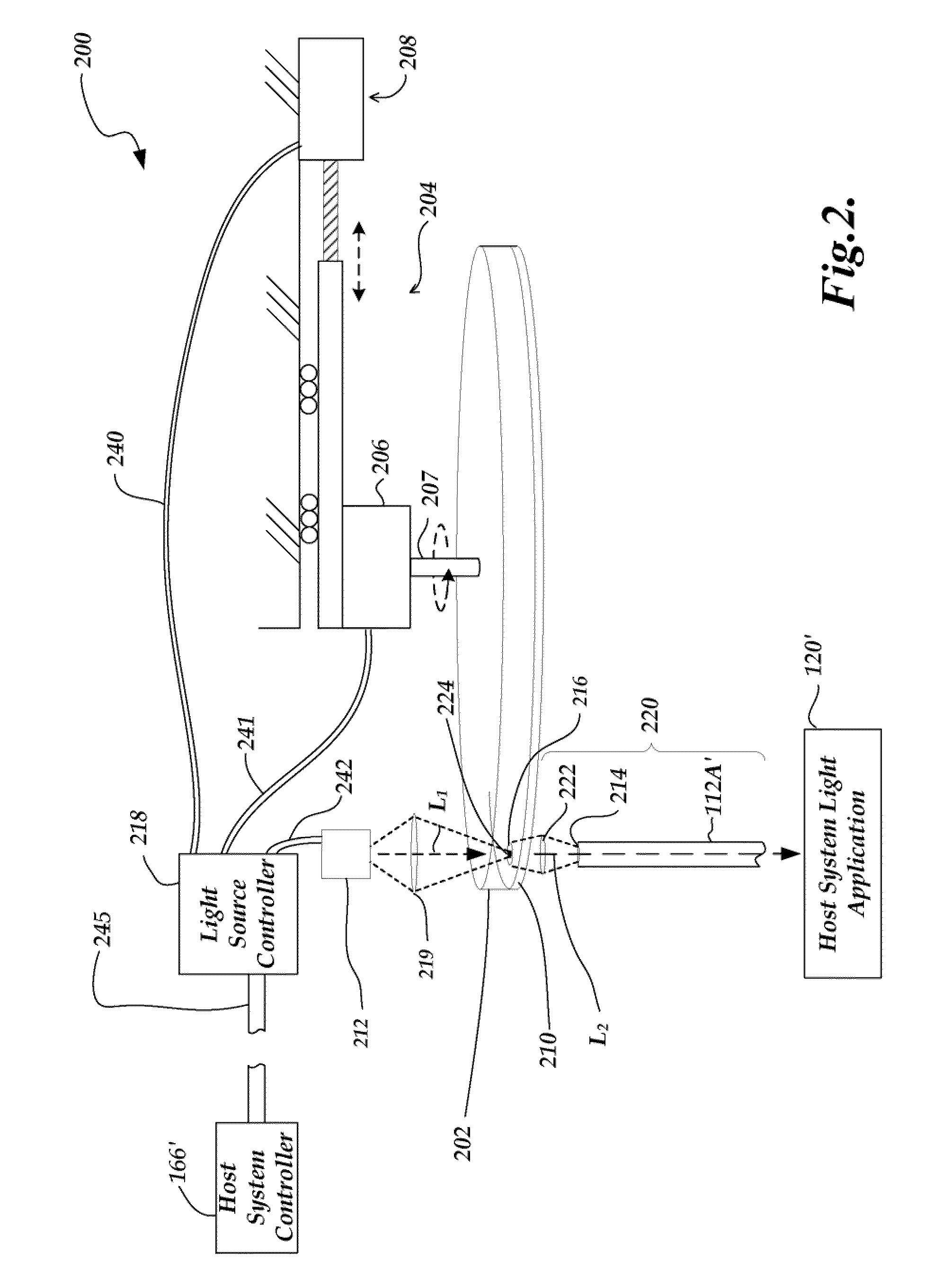
[0019]In some embodiments, the light source configuration comprises a light gathering mirror that generally surrounds the emitted light output coupling region and reflects and concentrates the emitted light to the entrance aperture of the output light path optical element set. In one embodiment, the light gathering mirror comprises an ellipsoidal mirror positioned with the illuminated spot approximately at one focus of the
ellipsoid and the entrance aperture of the output light path optical element at the other focus of the
ellipsoid. In another embodiment, the light gathering mirror comprises an off-axis
paraboloid mirror positioned to transfer the image of the illuminated spot to the entrance aperture of the output light path optical element. Various different light gathering mirrors may be configured to image the illuminated spot with a desired
magnification (e.g., a
magnification of 1 for a miniature
system and / or a single output
fiber, or a
magnification of 10 for an output
fiber bundle, and so on). In any case, a light gathering mirror allows a higher proportion of light emitted from the movable member to be collected and directed through the entrance aperture.
[0020]It should be appreciated that various embodiments of the invention provide a particularly compact and economical means for coupling
high intensity light into the end of an optical fiber. This is particularly valuable in applications (e.g., CPS applications,
collimated light projectors, and the like) that benefit from a high intensity “ideal
point source,” in that the output end of the optical fiber may provide an economical
point source that is nearly ideal (that is, it has a very small dimension) for many applications. Furthermore, various embodiments are able to provide various
wavelength spectra with improved versatility and economy compared to known methods for providing various spectra from a
point source. Furthermore, various embodiments are able to provide various pulse durations for various
wavelength spectra with improved versatility and economy compared to known methods for providing various pulsed spectra from a point source.

