
Rare earth-type tape-shaped oxide superconductor and a composite substrate used for the same

a composite substrate and oxide superconductor technology, applied in the direction of superconducting magnets/coils, superimposed coating processes, magnetic bodies, etc., can solve the problems of wire rod difficulty, slow production speed, and increase production costs, so as to prevent the deformation of the composite substrate, and increase the mechanical strength

Inactive Publication Date: 2010-04-22
SHOWA ELECTRIC WIRE & CABLE CO
View PDF7 Cites 14 Cited by
  • Summary
  • Abstract
  • Description
  • Claims
  • Application Information

AI Technical Summary

Benefits of technology

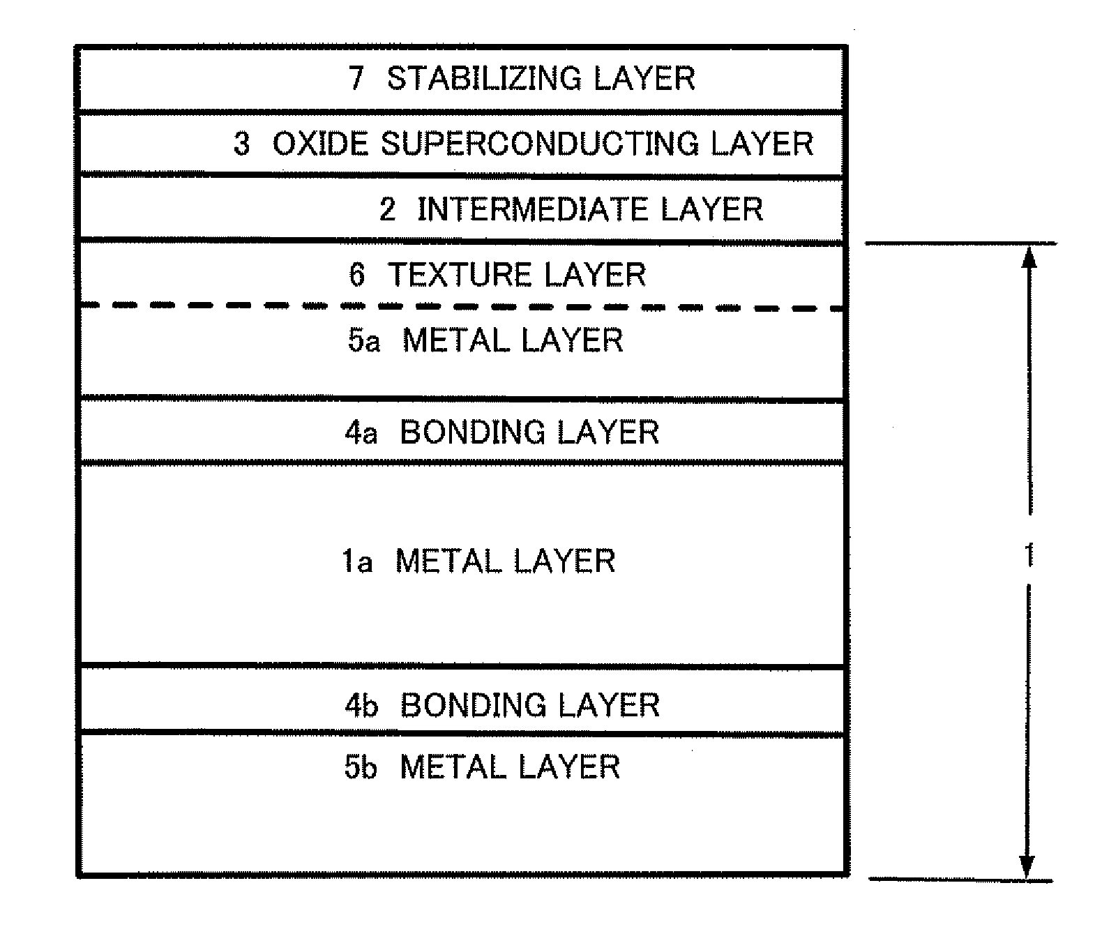
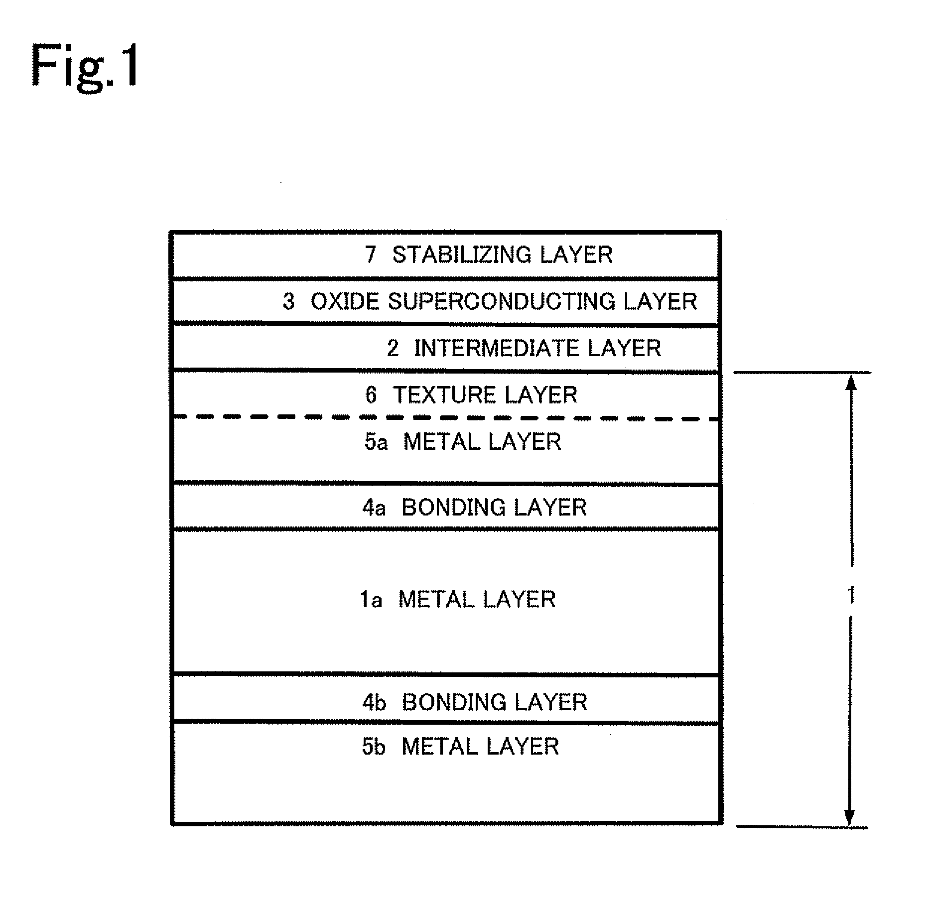
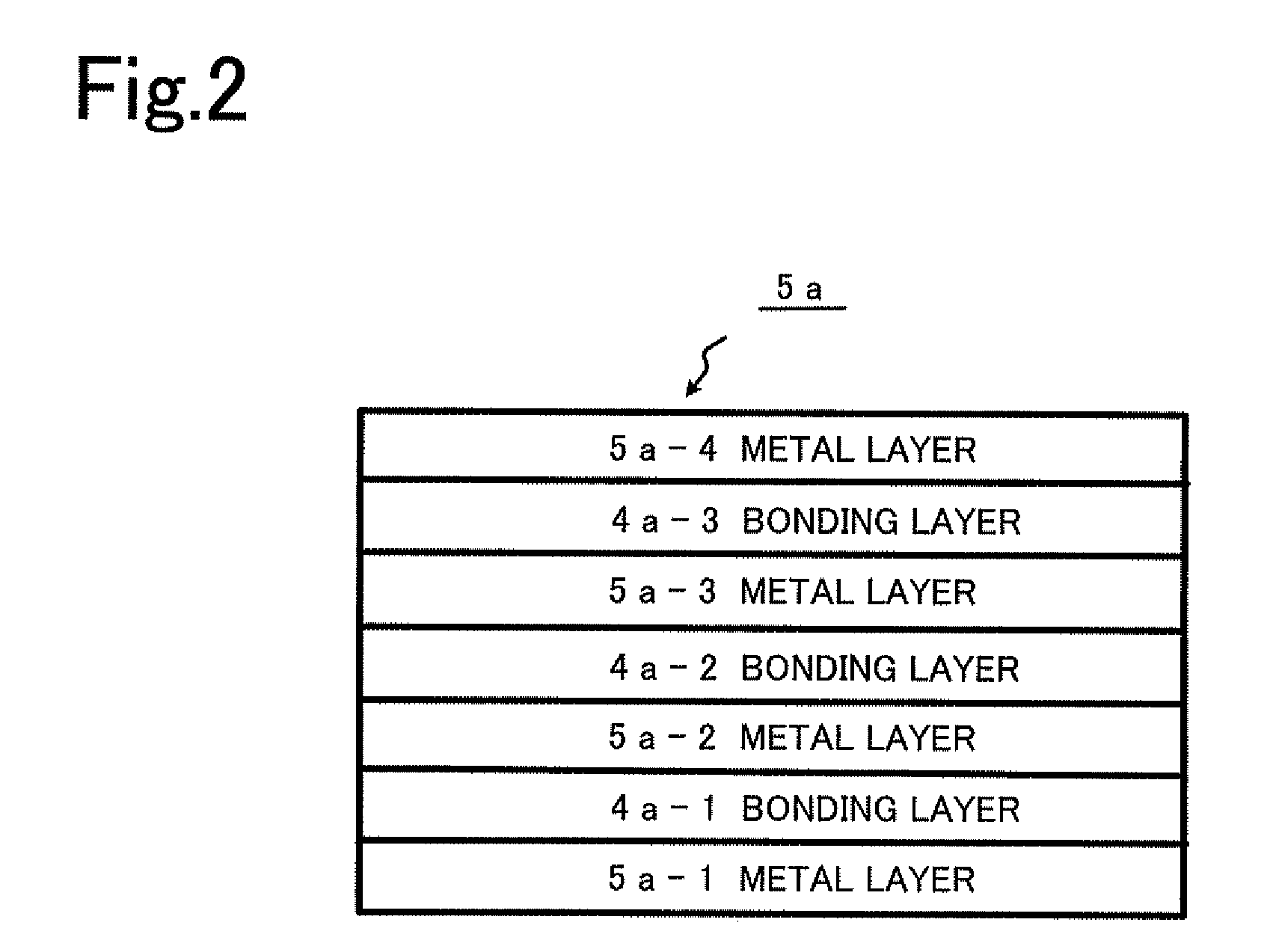
[0017]In addition, the campsite substrate which is used for the rare earth-type tape-shaped oxide superconductor of this invention comprises a metal substrate which becomes core material which is formed by non-oriented and non-magnetic metal, and comprises a first metal layer and a second metal layer which are arranged through a first bonding layer and a second bonding layer which are formed at both surfaces of this metal substrate by giving respectively a heat-treatment or a hot rolling after normal temperature bonding, and which has a function for preventing a deformation of the composite substrate. The first metal layer is formed by plural layers which have a function for preventing a diffusion of an element from a metal substrate, and at least the surface has a biaxially-oriented cubic texture, and a material which has a larger mechanical strength than the mechanical strengths of the first metal layer and second metal layer is used in the metal substrate.
[0018]According to this invention, the metal substrate which becomes the core material which is formed by non-oriented and non-magnetic metal, and the first meta...

Problems solved by technology

Therefore, the making of the wire rod has the difficulty compared with the Bi system oxide superconductor.
However, in this process, because all intermediate layers are formed by the vacuum process in the gas phase method, although this process has the advantage that the dense and smooth intermediate layer film can be obtained, there are problems that the production speed is slow and the production cost rises.
Although the processes of forming films by using sane gas phases other than this IBAD method have been studied, the effective means which solve the problems of the production speed and the production cost have not been reported.
Although this process is simple, because the long time heat-treatment in high temperature is necessary, according to the generation of cracks originating from the contraction in volume of film at the thermal decomposition, the non-uniform reaction by the imperfect of grain growth, and the decrease of the crystalline by such as the diffusion through the crystal grain boundary of the metallic element which constitutes the substrate, it was difficult to obtain the film having the function enough as the intermediate layer.
When this CeO2 intermediate layer is formed by MOD method, the cracks are generated depending on the large difference of the coefficient of thermal expansion with the metal of the substrate, and it becomes impossible to accomplish the function as the intermediate layer.
Although the generation of cracks is inhibited when the film is formed using the solid solution that Gd is added to CeO2 onto the Ni substrate by MOD method, because the diffusion of the element from Ni or Ni alloy substrate cannot be stopped in the inside of the intermediate layer, there was a problem that the superconducting property decreases.

Method used


Image

  • Rare earth-type tape-shaped oxide superconductor and a composite substrate used for the same
  • Rare earth-type tape-shaped oxide superconductor and a composite substrate used for the same
  • Rare earth-type tape-shaped oxide superconductor and a composite substrate used for the same

Examples


embodiment

[0039]As shown in FIG. 3, the non-oriented and non-magnetic Ni-9 at % W alloy tape 11 having the thickness of 30 μmt was bonded on the surface 10 of the non-oriented and non-magnetic hastelloy tape 100 having the thickness of 100 μmt and the non-oriented and non-magnetic Ni-9 at % W alloy tape 21 having the thickness of 60 μmt was bonded on the surface 20 of the hastelloy tape 100 by the normal temperature bonding process. After that, the Ni-3 at % W alloy tape 12 having the thickness of 30 μmt was bonded on the surface of the tape 11.

[0040]As for the tape 12, the predefined processing and heat-treatment was given so as to have the cubic texture.

[0041]The heat-treatment was given to the composite tape 101 of the four-layered structure which was bonded mutually in this way with 8 hours at 500° C. in the reduction atmosphere of Ar-4% H2, and the diffusion layers, that is, the bonding layers 50a, 50b and 50c were formed at the bonding interface of each layer. The thicknesses of these b...


PUM

PropertyMeasurementUnit
Currentaaaaaaaaaa
Mechanical strengthaaaaaaaaaa
Deformation enthalpyaaaaaaaaaa

Abstract

This invention provides a rare earth-type tape-shaped oxide superconductor having excellent mechanical strength and superconducting properties and a composite substrate using for the same. Non-oriented and non-magnetic Ni-9 at % W alloy tapes (11, 21) were bonded onto both sides of a non-oriented and non-magnetic hastelloy tape (100) by a normal temperature bonding process, and an Ni-3 at % W alloy tape (12) having a cubic texture was bonded onto the surface of the tape (11) by a normal temperature bonding process. Thereafter, the heat-treatment was given in a reducing atmosphere and a bonding layer (50a) etc. was formed on the adhesive interface of each layer. Next, a (Ce, Gd) O2 intermediate layer (13) and a Ce2Zr2O7 intermediate layer (14) by an MOD process, a CeO2 intermediate layer (15), a YBCO superconducting film (16) by a TFA-MOD method, and a silver stabilization layer (17) were stacked sequentially on the surface of the tape (12). A critical current value (Ic) of this superconductor showed 150 A.

Description

TECHNICAL FIELD[0001]This invention relates to an oxide superconductor and a composite substrate which are suitable to the usage for an electric power cable, an electric power device such as an electric power storage system, and power equipment such as a motor. In particular, this invention relates to a rare earth-type tape-shaped oxide superconductor which is suitable to the oxide superconductor manufactured by using a film formation method (hereinafter called MOD method) of forming a ceramics thin layer onto a substrate by heating and baking a precursor film, and relates to a composite substrate used for the rare earth-type tape-shaped oxide superconductor.BACKGROUND ART[0002]As for the oxide superconductor, a critical temperature (Tc) is high compared with a conventional alloy system superconductor such as Nb3Sn system, and applied equipments such as electric power cable, transformer, motor, and electric power storage system can be operated under the liquid nitrogen temperature. ...

Claims


Application Information

Patent Timeline
IPC IPC(8): H01B12/06
CPCC22C5/06C22C19/03C22C29/12H01L39/143H01L39/2454H01L39/2461Y10T428/12493C23C28/023C23C28/028C23C28/321C23C28/322C23C28/3455C23C28/36C23C28/021H10N60/203H10N60/0576H10N60/0632
Inventor AOKI, YUJIKOIZUMI, TSUTOMUTAKAHASHI, YASUOKANEKO, ATSUSHIHASEGAWA, TAKAYONAKAMURA, HIROSHI
Owner SHOWA ELECTRIC WIRE & CABLE CO
Learn More