
Process for a high efficiency and low emission operation of power stations as well as for storage and conversion of energy

Inactive Publication Date: 2010-04-29
TECHNIKUM CORP
View PDF9 Cites 59 Cited by
  • Summary
  • Abstract
  • Description
  • Claims
  • Application Information

AI Technical Summary

Benefits of technology

[0028]Task invention is developing a process for the production of electric energy in a with a mixture oxygen and natural gas driven low emission gas turbine and fluid turbine power station (GuF-power station) by using of overcapacity electric energy of the network and using of carbon dioxide as working fluid with additional using of geothermal potential, with a higher energy efficiency as before and avoiding known and described previous as well as other defects, connected with a simple construction based on low material technical effort. The task is solved by a process and a technical device to realize this process with a better utilization rate of the heat potentials in operating the power plant, the total avoidance of NOx-emission, a significant lower emission of carbon dioxide in the environment, a good control by the optimal using of given and changeable ambient temperatures, minimization of the exhaust heat and an optimal operation in connection with a significant improvement of the electrical efficiency as well as the possibility to store the electrical power from temporary overcapacities and, after change, to use effective for increasing the efficiency of the power plant in the normal operation and preferably for peak load supply.

Problems solved by technology

Disadvantageously at this technology is the high landscape consumption, the limitation to relatively few suitable locations and the high water losses by evaporation.
Disadvantageously are the high energy losses at the compression, the heavy heat emission and the low efficiency of the process.
Because in this case the costs of production of technical gases are in the focus of the interest, the loss of the compression heat is a usual and planned energy loss.
Other experiments for the using of buffer storages for electrical energy, e.g. in batteries, are in development but can not to be used in the process.
From the initiators of the project is judged, that the process is very energy intensive and had a low efficiency.
Besides the it is not easy to find usual locations for the storage.
Disadvantageously are the material technical problems caused by the aggressiveness of the ammonia-water-mixture which will be caused a lower life time of this few experienced process.
A second disadvantage is the possibility of the emission of the high toxic and environmental endangering ammonia by legs.
However the integration of this process is difficult and in such way there is not known practical examples therefore.
Other processes written in patents, are not technically realized at now.
The costs of compression for production of the higher working pressure are relatively high for this reason.
Disadvantageously is the separation into a working and a heat streaming circuit which are coupled by a heat exchanger too.
Subsequently are higher heat losses.
Advantageously at this process is the using of overcapacity energy producing accumulator of cold, disadvantageously is the use of a relatively high minimum temperature of more than 200° C. in the case of low temperature heat using as well as the relatively low used working pressure, seen energetically.
Further disadvantageously is the needed gas compression producing the working pressures.
At this process is the using of seawater disadvantageously, advantageously is the using of LNG, but it limits the operating conditions.
These processes are designing for using the cold potential of LNG for the vaporization and are not optimal to the power station process.
The complicated structure of the underground heat exchanger is disadvantageously in this process and the danger of a geothermal cool down of the surrounding of the storage is given.
Because no parameters in relation to temperature and pressure are given an exact assessment of the process is not possible.

Method used


Image

  • Process for a high efficiency and low emission operation of power stations as well as for storage and conversion of energy
  • Process for a high efficiency and low emission operation of power stations as well as for storage and conversion of energy

Examples


Embodiment Construction

OF APPLICATION

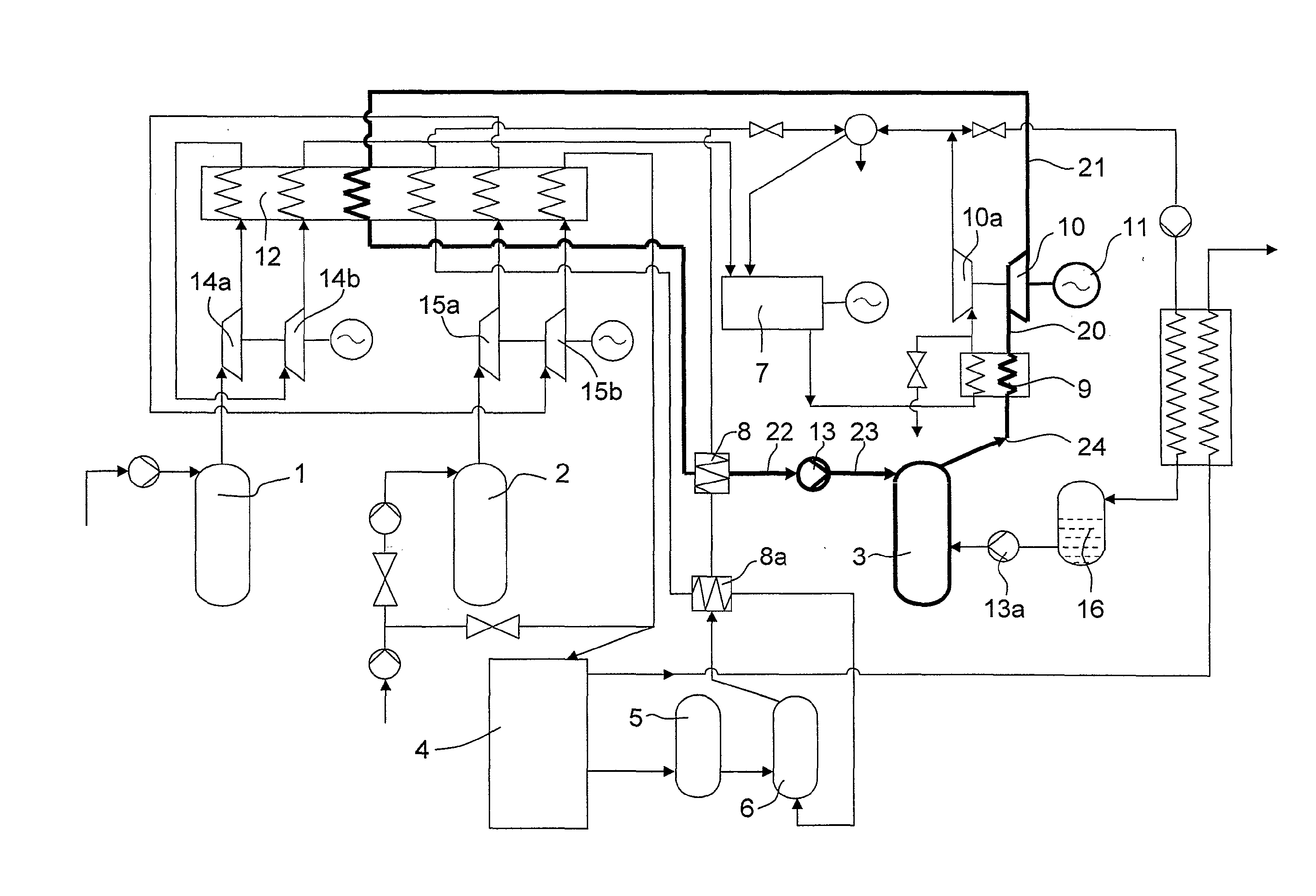
[0033]Further advantages are given by the description of an example of application of the invention by different temperatures of the using of heat with and without the using of a geothermic potential at 301 K as well as the connected figure and table with different modifications.

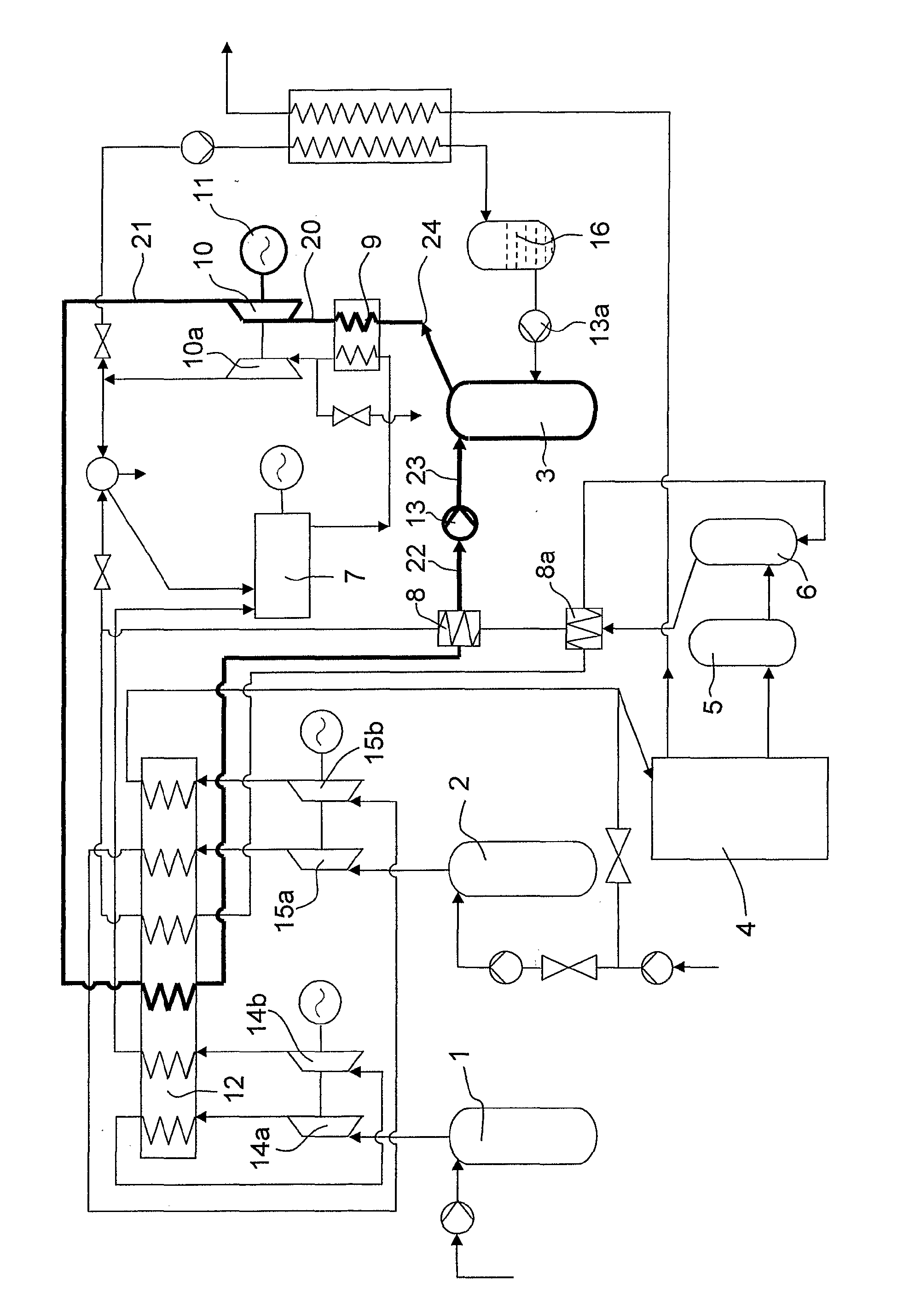
[0034]In the figure the principle of the construction of the device for the application of the process with using the geothermal potential is given schematically.

[0035]In the following example of the application the using of the decisive thermal potential is put into the centre of interest. The corresponding, with the numbers 20 to 24 characterized duct circuit is marked by increased lines. All of the other advantages are to understand by specialists direct and without other commentaries.

[0036]The most important parameters as transferred heats, temperatures and powers are given in the table in clearly visible form for the two temperatures 423 K and 473 K. The great advantage of the combination ...


PUM


Abstract

The invention relates to a process and a device for process realizing to increase the efficiency of power stations by improvement of the efficiency of using the heat potentials for an electric power production by using of supercritical carbon dioxide as a working fluid and heat transfer medium as well as for the improvement of the ecological balance of power stations by minimization of the carbon dioxide emission and the total avoidance of NOx-emissions by using of pure oxygen for the burning process. Additionally the process allows the buffering of electric overcapacity energy producing mass storages for natural gas, pressed air and carbon dioxide and their effective using as well as in the continuous operation and for peak load supply of power stations.

Description

[0001]The invention relates to a process and a technical device for a better using of heat potentials of a power station and its surrounding as well as connected plants with it for the reduction of carbon dioxide and NOx emissions in the environment as well as buffering and reusing of electric energy.FIELD AND BACKGROUND OF THE INVENTION[0002]The invention is characterized by a complex system of components to find a solution on the given requests in the energy sector. The plant concept has to fulfill the following aims in detail:[0003]Using of electrical overcapacities for foundation of mass storages and its using for reusing of electrical energy with a high efficiency.[0004]Creating a power station without emissions,[0005]Using the expansion energy and the connected different heat potentials with it for the production of electricity,[0006]Optimal using low temperature heat capacities for electric power generation,[0007]Using thermal energy potentials of connected plants for the inc...

Claims


Application Information

Patent Timeline
IPC IPC(8): F02C6/00
CPCF01K23/10Y02E20/16F01K25/103F25J3/04836F25J3/04018F25J3/04533F25J3/046F25J3/04612F25J2240/10F25J2245/40F25J2260/80F25J2290/62Y02E20/34F25J2240/90Y02E60/16
Inventor WESTMEIER, SIEGFRIED
Owner TECHNIKUM CORP
Learn More