Low embodied energy sheathing panels and methods of making same

a technology of low embodied energy and sheathing panels, applied in the direction of buttons, climate sustainability, solid waste management, etc., can solve the problems of poor indoor air quality, mold growth, unhealthy buildings, etc., and achieve the effect of reducing the environmental impact of its manufacture and high embodied energy

Inactive Publication Date: 2010-04-29
PACIFIC COAST BUILDING PRODS
View PDF99 Cites 21 Cited by
  • Summary
  • Abstract
  • Description
  • Claims
  • Application Information

AI Technical Summary

Benefits of technology

[0017]Thus, it would be highly desirable to meet all of the performance requirements of a structural sheathing panel while reducing the environmental impact of i

Problems solved by technology

The problems associated with excessive moisture in building wall cavities and the resulting mold growth, are well documented in the national outcry over unhealthy buildings and poor indoor air quality.
Wetting of exterior building surfaces and rainwater leaks are major causes of water infiltration, but so is excessive indoor moisture generation.
Moisture may be present within a structure due to occupancy and use by humans, use of wet materials during construction, air leaks, or transportation by external wall materials.
If these guidelines are not observed, the structure is at risk of allowing water vapor condensation within the wall cavity.
However, OSB would be deemed unacceptable in the same assembly.
Gypsum sheathing does not hold peel and stick water barrier well.
Unfortunately, the structural integrity of plywood is dependent upon the inclusion of quality wood laminates harvested from mature, large diameter trees, at least 30 years old.
Their manufacture puts stress on old growth forests and existing woodland areas.
In addition, their costs have risen over the last decade, making them less desirable as a mainstay construction material.
Although the aspen wood is not a rapidly renewable resour

Method used


Image

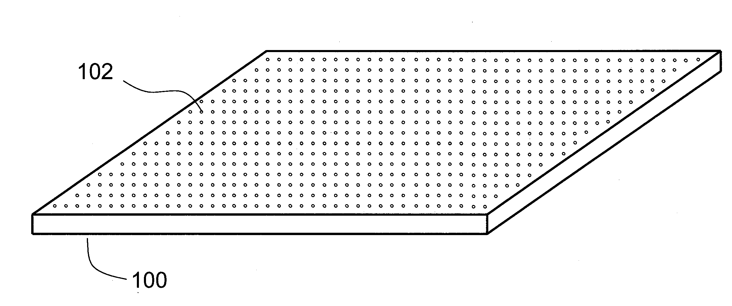
  • Low embodied energy sheathing panels and methods of making same
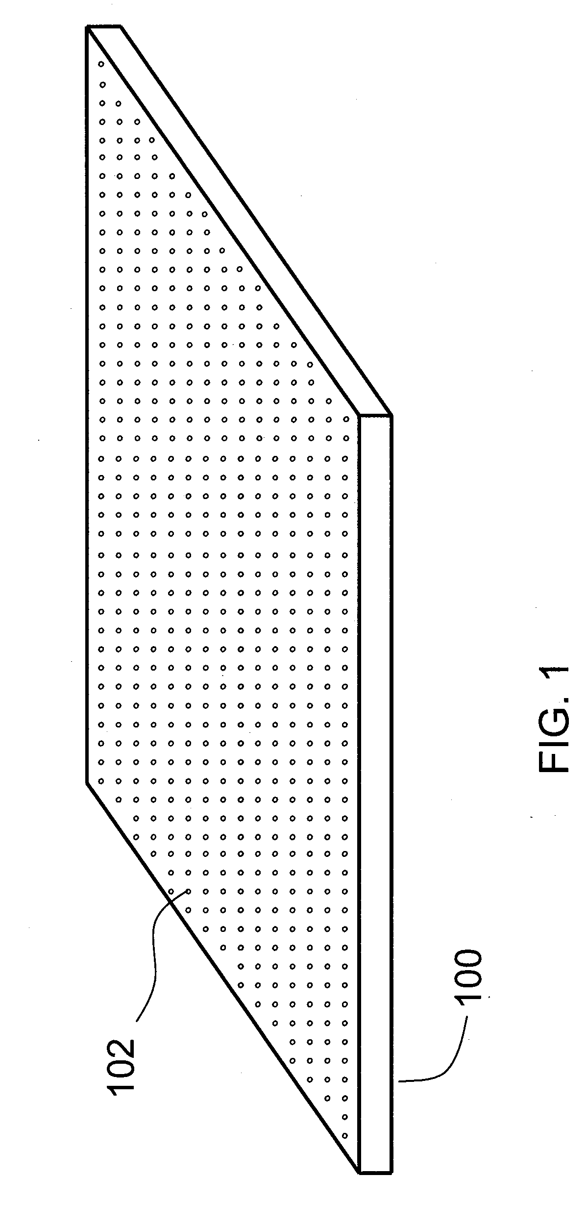
  • Low embodied energy sheathing panels and methods of making same
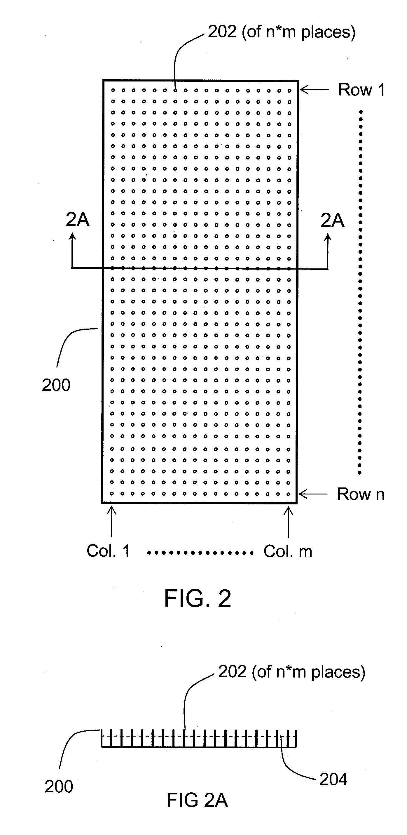
  • Low embodied energy sheathing panels and methods of making same

Examples


Embodiment Construction

[0025]The following detailed description of embodiments of the invention is illustrative only and not limiting. Other embodiments will be obvious to those skilled in the art in view of this description. The example embodiments are in such detail as to clearly communicate the invention. However, the amount of detail offered is not intended to limit the anticipated variations of embodiments; but, on the contrary, the intention is to cover all modifications, equivalents, and alternatives falling within the spirit and scope of the present invention as defined by the appended claims. Various changes in the details may be made without departing from the spirit, or sacrificing any of the advantages of the present invention. The detailed descriptions below are designed to make such embodiments obvious to a person of ordinary skill in the art.

[0026]The novel processes as described herein for manufacturing a low embodied energy novel sheathing panel lessen the environmental impact created by ...


PUM

PropertyMeasurementUnit
Fractionaaaaaaaaaa
Fractionaaaaaaaaaa
Fractionaaaaaaaaaa

Abstract

Sheathing panels are produced by methods which do not require natural resources such as wood and use significantly reduced embodied energy when compared with the energy used to fabricate gypsum sheathing panels. A novel binder, consisting in one embodiment of monopotassium phosphate and magnesium oxide, and combined with various fillers, is used to provide a controlled exothermic reaction to create a gypsum board-like core which can be formed into a suitable sheathing panel handled and installed in a typical manner. The panel is manufactured to have a desirable shear resistance and water vapor permeability, important performance elements in building envelope design. The manufacturing process results in a panel that does not require mature trees as source material, does not off gas, and involves much lower greenhouse gas emissions than the processes used to make traditional wood or gypsum-based sheathing panels.

Description

FIELD OF INVENTION[0001]The present invention relates to new compositions and methods of manufacture for sheathing panels and in particular to panels and processes which reduce the energy required to manufacture such a sheathing panel when compared to the energy required to manufacture traditional gypsum or wood-based sheathing panels.BACKGROUND OF THE INVENTION[0002]In the field of building construction, structural sheathing is a crucial element in suitable building design. It may serve many functions associated with the purpose and integrity of the assembly, including strengthening the building to lateral forces; providing a base wall to which finish siding can be nailed; acting as thermal insulation; and, in some cases, acting as a base for further thermal insulation. Sheathing, in the form of thin, rigid panels is nailed directly onto the framework of the building. Some common types of sheathing include wood boards or slats, oriented strand board (OSB) panels, plywood panels, an...

Claims


Application Information

Patent Timeline
IPC IPC(8): B32B3/26C04B38/00C04B20/00B28B1/14B28B1/48
CPCB28B1/48B28B7/186C04B28/34C04B2111/00267C04B2111/0062C04B14/02C04B14/043C04B14/28C04B18/24C04B22/0013C04B22/064C04B40/0259C04B14/18C04B14/308C04B14/42C04B18/08C04B18/248C04B20/002C04B40/0608C04B14/301C04B14/304C04B16/0675Y02W30/91
Inventor SURACE, KEVIN J.TINIANOV, BRANDON D.
Owner PACIFIC COAST BUILDING PRODS
Why Eureka
Try Eureka