Plasma process apparatus

a plasma process and plasma technology, applied in the direction of chemical vapor deposition coating, electric discharge tube, coating, etc., can solve the problems of difficult to produce high density plasma at relatively low pressure in the rf plasma apparatus, low etching rate, and more damage to device elements on the wafer, so as to improve the performance or quality of the plasma process, improve the uniformity and controllability of plasma density, and be easily monitored

Inactive Publication Date: 2010-04-29
TOKYO ELECTRON LTD
View PDF11 Cites 291 Cited by
  • Summary
  • Abstract
  • Description
  • Claims
  • Application Information

AI Technical Summary

Benefits of technology

[0035]According to embodiments of the present invention, a plasma process apparatus that can prevent abnormal discharging in a microwave transmission line or radiation path, or a process gas ejection portion, is provided, so that plasma excellent in p...

Problems solved by technology

However, it is difficult to produce high density plasma at relatively low pressures in the RF plasma apparatus.
In addition, it is disadvantageous in that device elements on a wafer are more frequently damaged during the plasma process because the RF plasma inherently has high electron temperatures.
In the first configuration, while it is advantageous in that the plasma can be uniformly produced above the susceptor, the plasma density tends to be lower, which leads to a low etching rate when the plasma process apparatus is an etcher, and an inefficient process as a whole.
In addition, such a configuration may cause a problem of contamination or the like.
On the other hand, in the second configuration, ...

Method used


Image

  • Plasma process apparatus
  • Plasma process apparatus
  • Plasma process apparatus

Examples


first embodiment

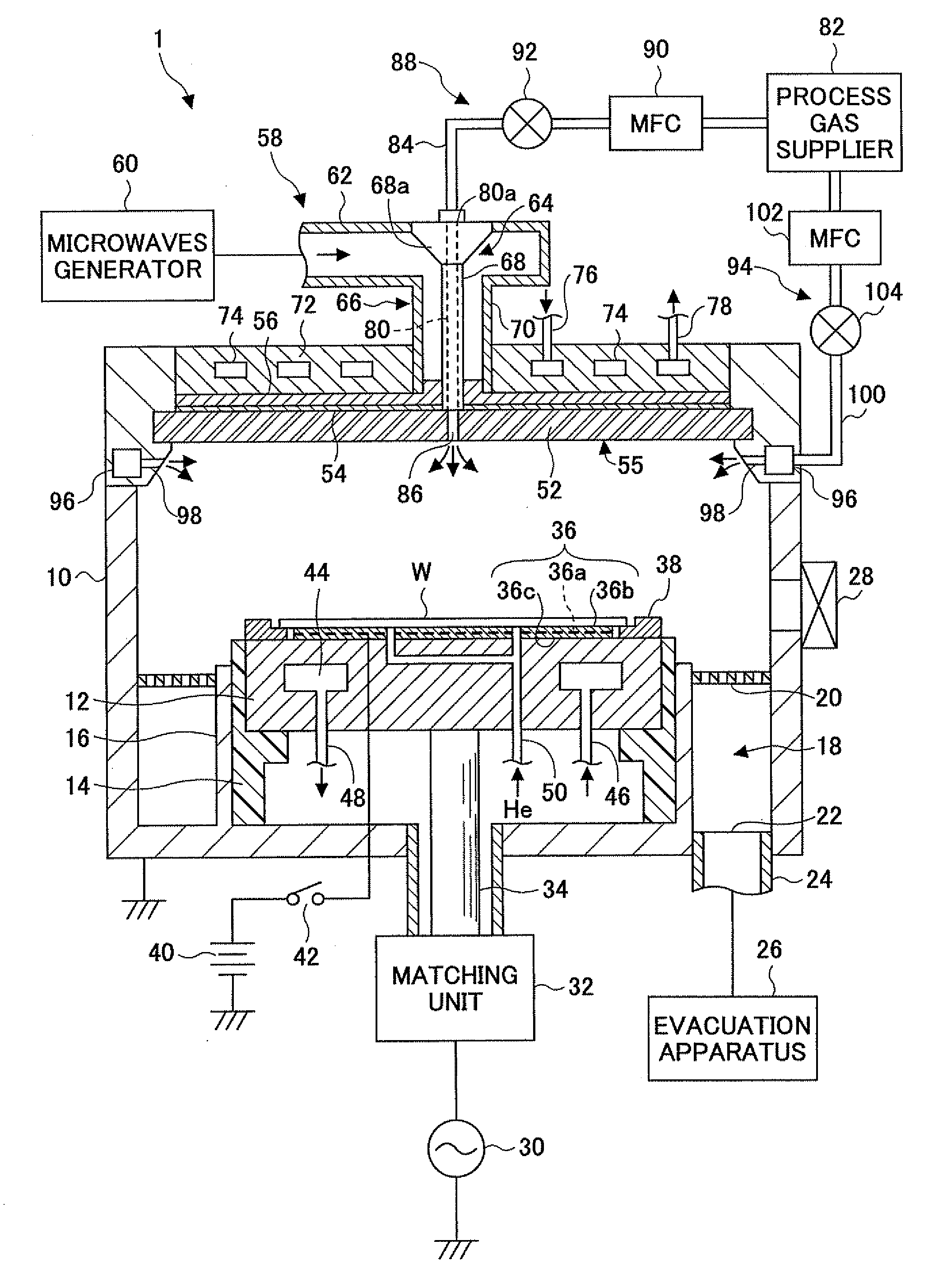
[0047]FIG. 1 is a schematic cut-open view of a microwave plasma etching apparatus 1 according to a first embodiment of the present invention. The microwave plasma etching apparatus 1, which is configured as a planar SWP type plasma process apparatus, has a cylinder-shaped chamber (process chamber) 10 made of metal such as aluminum or stainless steel. The chamber 10 is grounded for security reasons.

[0048]First, components or members, which do not directly contribute to generating the microwave plasma in the chamber 10 of the microwave plasma etching apparatus 1, are described.

[0049]In a lower center portion of the chamber 10, there is a susceptor 12 on which a semiconductor wafer W (referred to as a wafer W below) is placed. The susceptor 12 is horizontally supported by a cylindrical supporting portion 14 extending upward from the bottom of the chamber 10. The cylindrical supporting portion 14 is made of an insulating material. Additionally, the susceptor 12 is shaped into a circular...

second embodiment

[0078]Referring to FIGS. 6 through 9, a plasma process apparatus according to a second embodiment of the present invention is described. FIG. 6 is a schematic cut-open view of the plasma process apparatus 2 according to the second embodiment of the present invention. While the plasma process apparatus 2 according to the second embodiment is operated, when etching the wafer W in substantially the same manner as the plasma process apparatus 1 according to the first embodiment, the plasma process apparatus 2 is different in a gas ejection configuration at the top center portion of the chamber 10 from the plasma process apparatus 1 according to the first embodiment of the present invention. The following explanation is focused on the difference.

[0079]As shown in FIG. 6, the gas conduit 80 goes through the inner conductor 68 of the coaxial pipe 66, and the top portion of the gas conduit 80 is connected to the process gas supplier 82 through the first gas supplying pipe 84, which places t...


PUM

PropertyMeasurementUnit
Distanceaaaaaaaaaa
Temperatureaaaaaaaaaa
Thicknessaaaaaaaaaa

Abstract

A disclosed a plasma process apparatus includes a process chamber that houses a substrate subjected to a predetermined plasma process and may be evacuated to a reduced pressure; a microwave generator that generates microwaves for generating plasma; a waveguide pipe that transmits the microwaves from the microwave generator to the process chamber; a waveguide pipe/coaxial pipe converter connected to one end of the waveguide pipe; and a coaxial pipe that forms a line through which the microwaves are transmitted from the waveguide pipe-coaxial pipe converter to the process chamber. An inner conductive body of the coaxial pipe has a hollow portion; and a first process gas supplying portion that supplies a process gas into the process chamber through the hollow portion of the inner conductive body of the coaxial pipe.

Description

TECHNICAL FIELD[0001]The present invention relates to a microwave plasma process apparatus that utilizes microwaves so as to carry out a predetermined plasma process, specifically to a microwave plasma process apparatus that supplies microwave power to plasma in a process chamber through electromagnetic wave coupling.BACKGROUND ART[0002]In plasma processes for fabricating semiconductor devices, liquid crystal displays (LCD), and the like, radio frequency (RF) waves and microwaves are used so as to discharge or ionize a process gas in a vacuum process chamber. An RF plasma apparatus mainly employs capacity coupling where a pair of electrodes is located, one electrode in parallel with the other leaving an appropriate gap between the electrodes in the process chamber. The RF waves are applied to one of the electrodes through a capacitor while the other electrode is grounded. However, it is difficult to produce high density plasma at relatively low pressures in the RF plasma apparatus. ...

Claims


Application Information

Patent Timeline
IPC IPC(8): H01L21/465
CPCH01J37/32192H01J37/32229H01J37/32449C23C16/511H01J37/3244
Inventor IWASAKI, MASAHIDE
Owner TOKYO ELECTRON LTD
Why Eureka
Try Eureka