

Two-step formation of hydrocarbon-based polymer film
a polymer film and hydrocarbon-based technology, applied in the field of hydrocarbon-based polymer film formation, can solve the problems of difficult control of refractive index and extinction coefficient of the formed films, and the difficulty of forming thin films on the substrate using this method, etc., to achieve low extinction coefficient, high density, and mechanical strength.
- Summary
- Abstract
- Description
- Claims
- Application Information
AI Technical Summary
Benefits of technology
Problems solved by technology
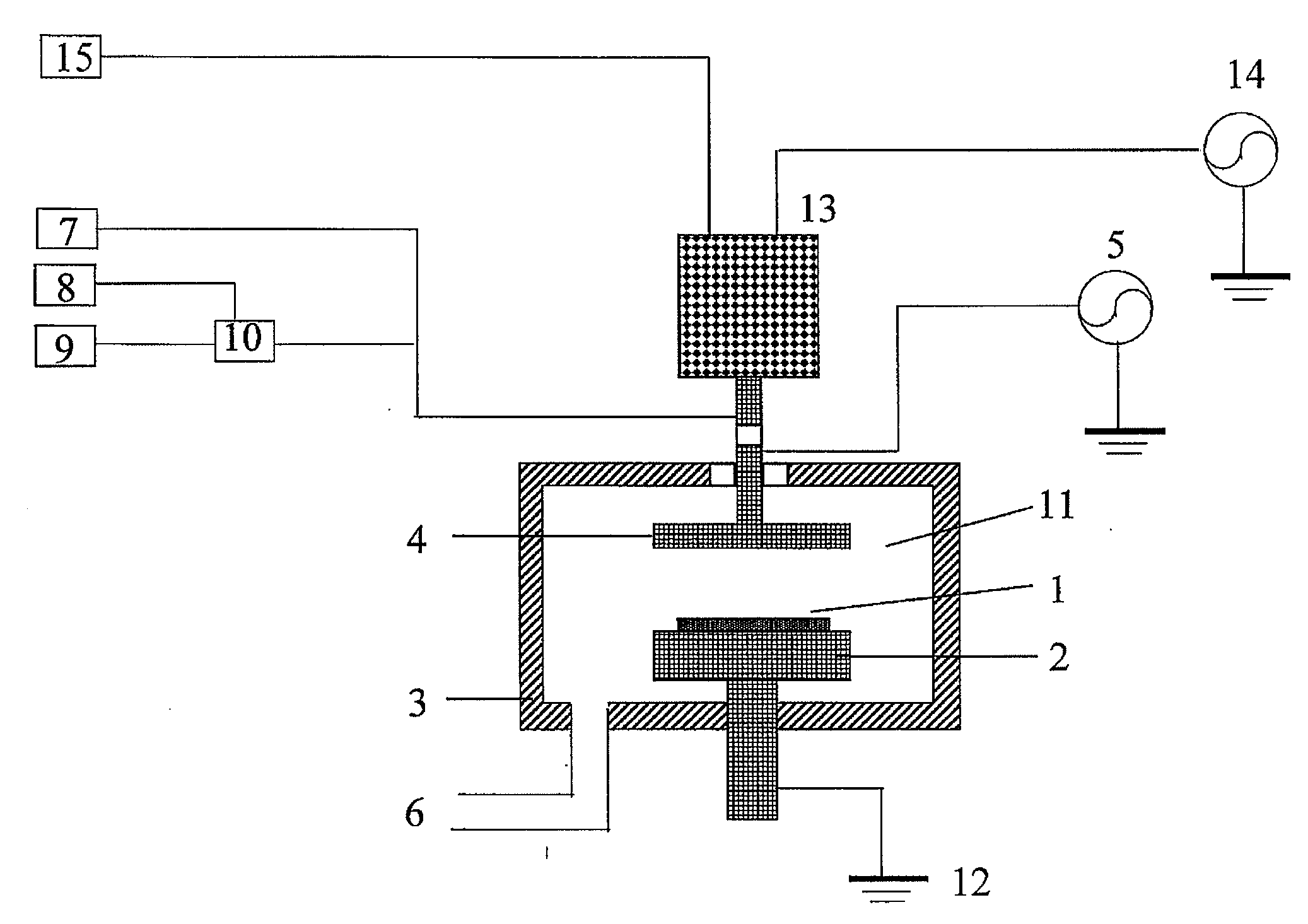
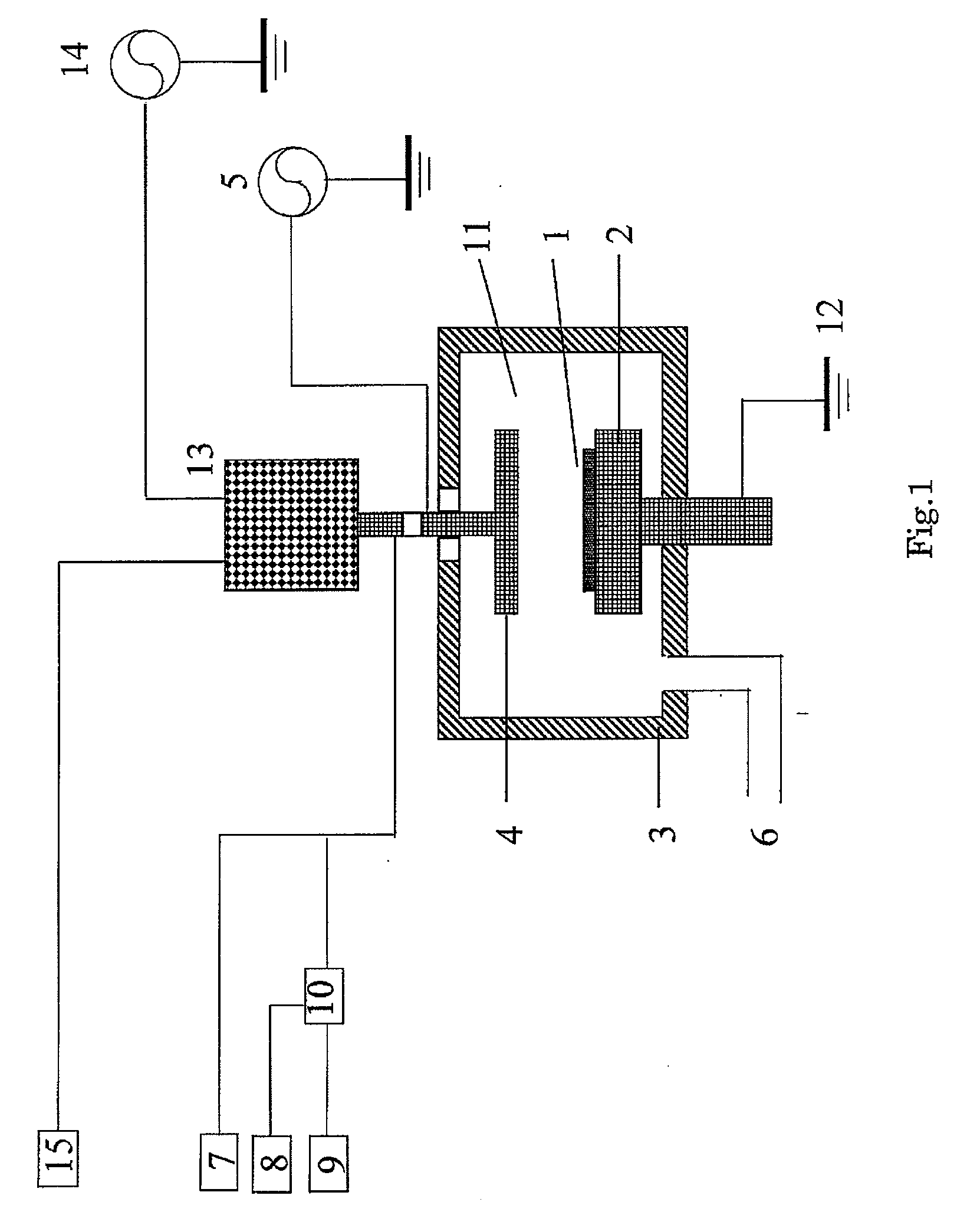
Method used
Image

Examples
example 1
[0104]Process conditions in this example and film formation results are shown as follows:
[0105]Process Parameter and Set Points:
Principal filmParametersforming StepMesitylene120 sccmHe400 sccmAr2000 sccmProcess Pressure500 PaHRF Power1800 WSubstrate Temperature340° C.Electrode spacing16 mmProcess time18.5 sec.
[0106]He supplied to vaporizer: 500 sccm
[0107]Temperature of vaporizer, vaporizer portion: 150° C.
[0108]Controlled temperature of gas inlet piping: 150° C.
[0109]Film Formation Results:
[0110]Thickness: 22 4 nm
[0111]RI(n)@633 nm: 1.83
[0112]Extinction coefficient (k) @633 nm: 0.05
[0113]Film Stress: −174 MPa
[0114]Modulus: 33.35 GPa
[0115]Hardness: 4.57 GPa
[0116]Density: 1.29 g / cm3
[0117]The film formed using above conditions (Example 1) shows fairly good film properties. However, it has a poor film stability performance. FIG. 3 is a graph showing the relationship between film stress and elapsed time of the hydrocarbon-based polymer film obtained above (“w / o APT”). FIG. 4 is a graph ...
example 2
[0118]Process conditions in this example were the same as in Example 1 except that a He plasma treatment step was implemented after the principal film formation step.
[0119]Process Parameter and Set Points:
Principal filmHe PlasmaParametersforming StepTreatmentMesitylene120 sccm0 sccmHe400 sccm2.5 slmAr2000 sccm0 sccm (No flow)Process Pressure500 Pa500 PaHRF Power1800 W1800 WSubstrate Temperature340° C.340° C.Electrode spacing16 mm16 mmProcess time18.5 sec.10 sec.
[0120]Film Formation Results:
[0121]Thickness: 231 nm
[0122]RI(n) @ 633 nm: 1.82
[0123]RI(k) @ 633 nm: 0.05
[0124]Film Stress: −178 MPa
[0125]Modulus: 33.6 GPa
[0126]Hardness: 4.47 GPa
[0127]Density: 1.28 g / cm3
[0128]The film formed using the He plasma treatment shows fairly good film properties. However, as shown in FIGS. 3 and 4, the film obtained above (“w / He Plasma”) has a unreliable film stability performance, and no improvements were observed as compared with the film of Example 1.
example 3
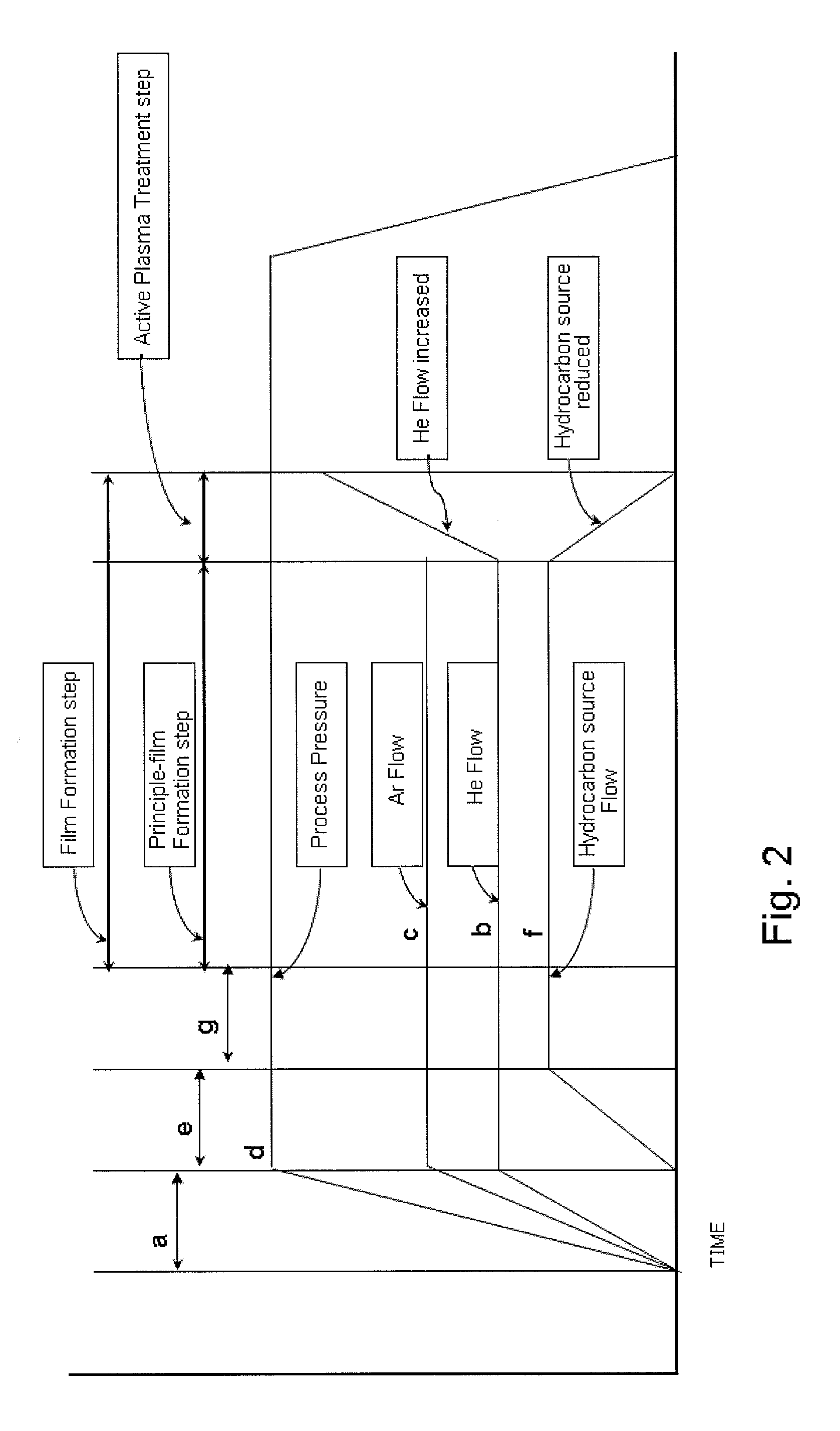
[0129]Process conditions in this example were the same as in Example 1 except that an active plasma treatment step was implemented after the principal film formation step.
[0130]Process Parameter and Set Points:
Principal filmParametersforming StepActive Plasma TreatmentMesitylene120 sccmLinearly Reduced to 0 sccmHe400 sccmLinearly Increased to 2.5 slmAr2000 sccm0 sccm (No flow)Process Pressure500 Pa500 PaHRF Power1800 W1800 WSubstrate Temperature340° C.340° C.Electrode spacing16 mm16 mmProcess time18.5 sec.10 sec.
[0131]Film Formation Results:
[0132]Thickness: 231 nm (The thickness of the principal film: 223 nm; the active plasma treated film: 8 nm)
[0133]RI(n)@633 nm: 1.82
[0134]RI(k)@633 nm: 0.05
[0135]Film Stress −168 MPa
[0136]Modulus: 36.6 GPa
[0137]Hardness: 5.17 GPa
[0138]Density: 1.39 g / cm3
[0139]The film formed using the active plasma treatment step shows an excellent film property. As shown in FIG. 5, elastic modulus of the film of Example 3 (“w / APT”) was improved by more than 10%...
PUM
| Property | Measurement | Unit |
|---|---|---|
| Thickness | aaaaa | aaaaa |
| Thickness | aaaaa | aaaaa |
| Thickness | aaaaa | aaaaa |
Abstract
Description
Claims
Application Information