Battery charger

a battery charger and battery technology, applied in the field of battery chargers, can solve the problems of relatively long charging time and environmental pollution, and achieve the effects of reducing charging time and installation cost, improving infrastructure for charging secondary batteries, and effectively improving charging efficiency

Inactive Publication Date: 2010-04-29
KYUSHU ELECTRIC POWER CO INC
View PDF3 Cites 126 Cited by
  • Summary
  • Abstract
  • Description
  • Claims
  • Application Information

AI Technical Summary

Benefits of technology

[0019]In the present invention, as an improvement in infrastructure for charging of secondary batteries, the plurality of DC stabilized power supply circuits are provided in the DC power supply section to allow an electric power supply line to be configured as a plurality of independent lines, so that electric powers to be supplied to respective ones of a plurality of secondary batteries can be adjusted individually. This makes it possible to charge a plurality of secondary batteries which are used in different types of apparatuses, such as an electric vehicle and a mobile power supply unit, in a simultaneous or concurrent manner, and charge the secondary batteries according to a desired battery-charge mode, such as the rapid charge mode, which is arbitrarily input from the input section in advance, without relation to conditions of the control section of battery charger
[0020]In the present invention, the number and respective outputs of the DC stabilized power supply circuits can be adjusted depending on the number and respective charging conditions of the secondary batteries to be concurrently charged.
[0021]In the present invention, an output of each of the DC stabilized power supply circuits can be optimally maintained without a need for a large-capacity DC power supply circuit.
[0022]In the present invention, only one of the secondary batteries can be selectively charged in the rapid charge mode, or two or more of the secondary batteries can be selectively charged in the rapid charge mode. This makes it possible to effectively improve charging efficiency, and effectively reduce a charging time and an installation cost.
[0023]Further, even if a trouble occurs in one of the DC stabilized power supply circuits, a remaining one of the DC stabilized power supply circuits can be used as its backup. The DC stabilized power supply circuits may be separated from remaining components of the battery charger, and remote-controlled. For example, only the connection sections for the secondary batteries and the input sections each adapted to allow an operator or user to set up / input charging conditions may be installed in a battery-charge area, while arranging the DC stabilized power supply circuits on a column, or below the ground, or in another site, so as to facilitate effective utilization of the battery-charge area. Thus, in case where a plurality of secondary batteries mounted to respective electric vehicles are charged, the battery charger can concurrently charge the secondary batteries while effectively reducing a charging time, under a condition that it is installed in a relatively narrow space, as long as the space is enough to park the electric vehicles.
[0024]Each of the battery-charge operating devices may have a function of accessing an information communication system. In this case, an operator or user can pay a fee by a credit card, or use an information communication service, such as an Internet service, during a waiting period, i.e., during a charging operation, to facilitate effective utilization of the waiting period. This makes it possible to effectively enhance a function of a facility as a service station.

Problems solved by technology

A vehicle with a gasoline engine or a diesel engine causes environment pollution, due to CO2, NOx, black smoke or harmful particulate matter which is contained in exhaust gas discharged therefrom.
Developments of the secondary battery, such as reduction in size and weight, and increase in battery capacity, are regarded as an urgent challenge to expand use of battery-operated electric apparatuses including electric vehicles.
However, as another challenge to expand use of the secondary battery, there exists a problem of a relatively long charging time.
Along with the developments of the secondary battery, there is an increasing need for enhancing a function of a battery-charging facility or station, and technical developments for a battery-charging station capable of readily charging a secondary battery, e.g., in the rapid charge mode, also become a critical challenge.

Method used


Image

  • Battery charger
  • Battery charger
  • Battery charger

Examples


first embodiment

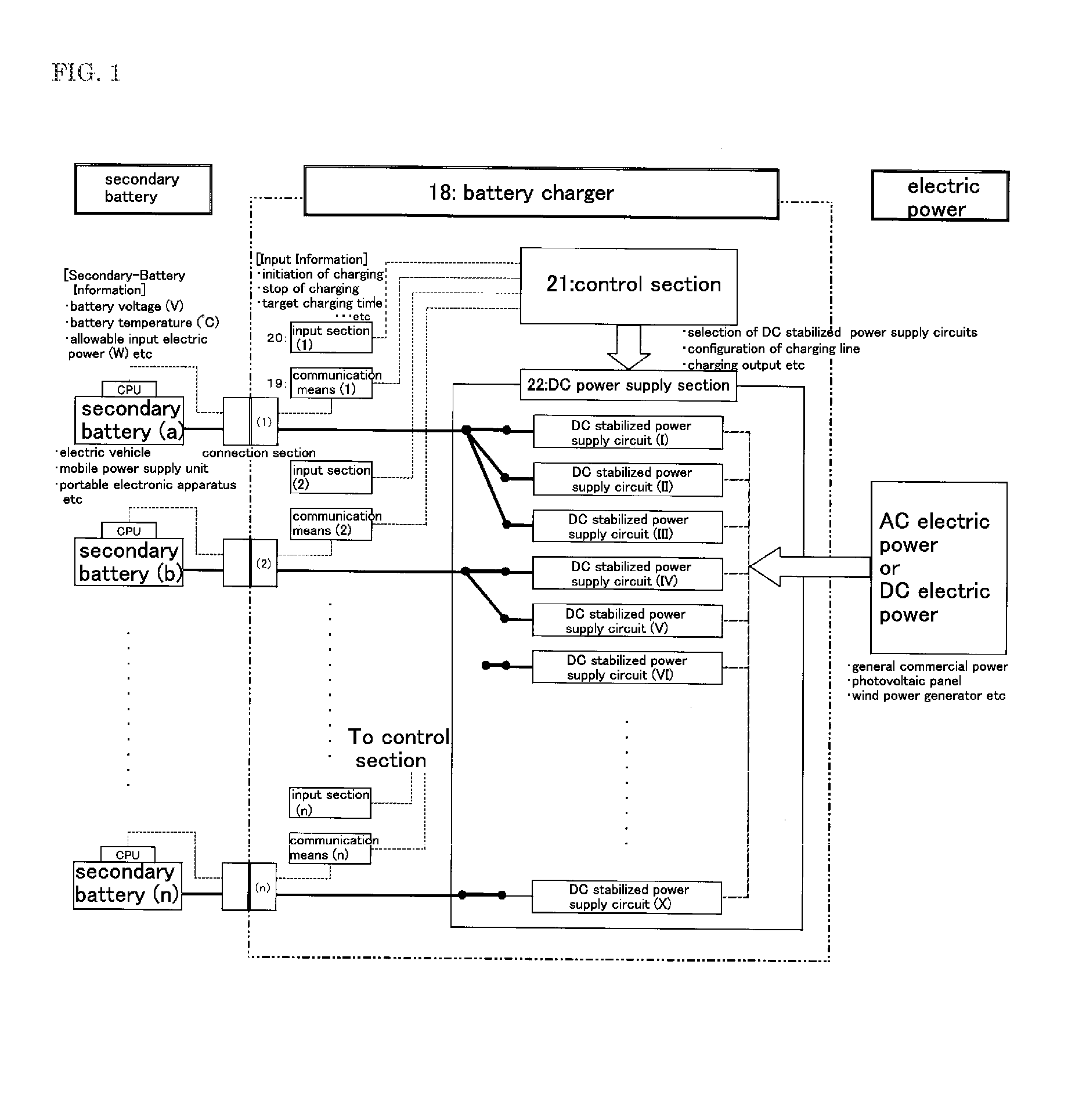
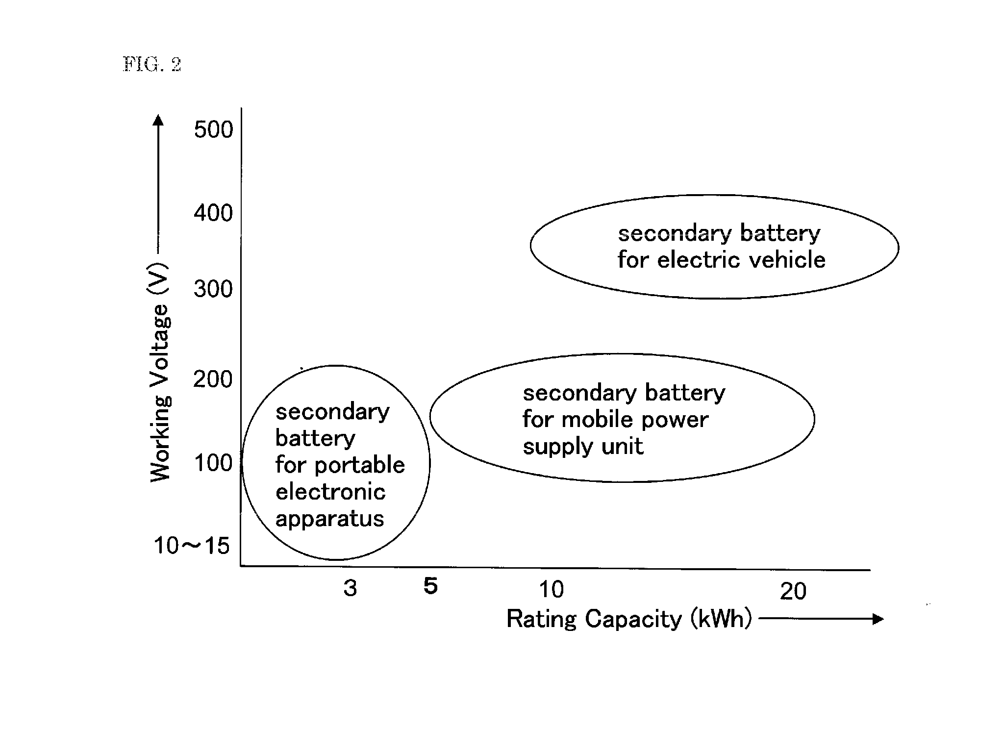
[0026]FIG. 1 is a block diagram showing an operation of a battery charger according to a first embodiment of the present invention, and FIG. 2 is a chart showing an example of a secondary battery capable of using a battery charger of the present invention.

[0027]A plurality of secondary batteries (a) to (n) are connected to the battery charger through respective ones of a plurality of connection sections (1) to (n). Each of the secondary batteries (a) to (n) is also connected to a control section 21 through communication means 19, to allow secondary-battery information held by a CPU mounted in each of the secondary batteries (a) to (n), such as a battery voltage (V), a battery temperature (° C.) and an allowable input electric power value (W), to be transmitted to the control section 21.

[0028]For example, the secondary battery includes: a secondary battery for an electric vehicle, which has an operating voltage of about 350 V and a rating capacity of about 10 to 25 KWh; a secondary b...

second embodiment

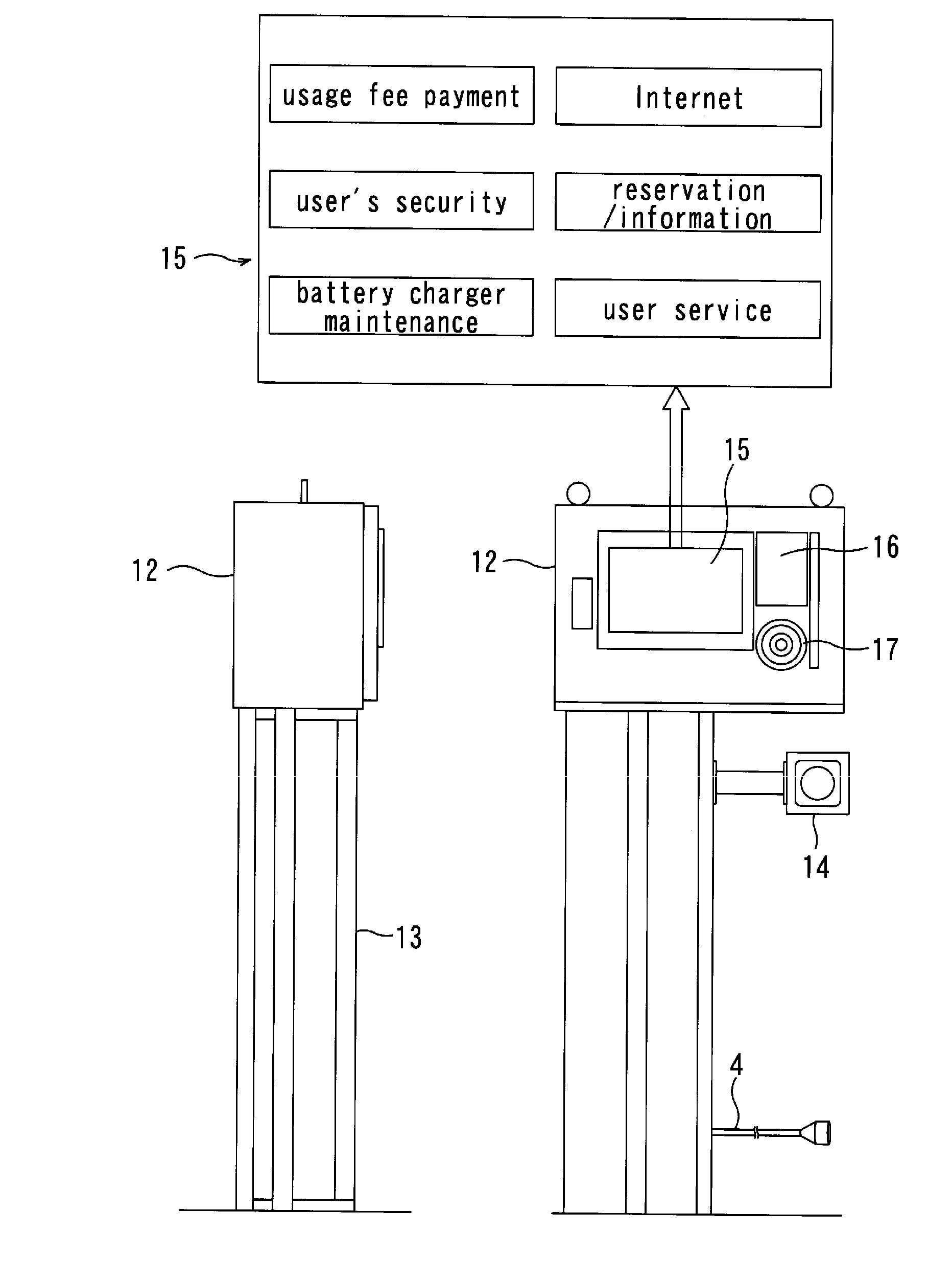
[0036]FIG. 3 is an overall view schematically showing an electric vehicle battery charger according to a second embodiment of the present invention.

[0037]The electric vehicle battery charger (hereinafter referred to simply as “battery charger”) comprises a DC power supply section 1 installed on an upper portion of an installation column 2 provided in a site to extend vertically upwardly from the ground, and a plurality of battery-charge operating devices 3 each installed on the ground. Each of the battery-charge operating devices 3 includes a charging feed cable 4 adapted to be connected to a secondary battery of an electric vehicle to charge the secondary battery. The DC power supply section 1 is adapted to be supplied with electric power from a transformer 6 on a utility-line pole 5 or an underground transformer (not shown) via a feed cable 7, such as an aerial service line or an underground cable line, or to be supplied with electric power from a storage power supply facility, su...


PUM

PropertyMeasurementUnit
total weightaaaaaaaaaa
operating voltageaaaaaaaaaa

Abstract

The present invention provides a battery charger capable of charging a plurality of secondary batteries which are used in different types of apparatuses, such as an electric vehicle and a mobile power supply unit, in a simultaneous or concurrent manner without largely occupying an installation space on the ground. A DC power supply section 22 includes a plurality of DC stabilized power supply circuits each operable to supply an output according to required electric power, therefrom in an independent manner. Specifically, based on information from each of a plurality of secondary batteries, and information set up/input through a setup/input section, one of or a combination of two or more of the DC stabilized power supply circuits is selected for each of the secondary batteries. Then, an electric power supply line between the selected one of or the selected combination of two or more of the DC stabilized power supply circuits and each of the secondary batteries to be charged is configured, and an output of the selected one of or the selected combination of two or more of the DC stabilized power supply circuits is adjusted. This makes it possible to configure respective electric power supply lines for the secondary batteries to allow the secondary batteries to be concurrently charged, and adjust respective electric power amounts to be supplied to the secondary batteries, individually.

Description

TECHNICAL FIELD[0001]The present invention relates to a battery charger capable of simultaneously supplying electric powers to a plurality of secondary batteries, respectively, as required by respective ones of the secondary batteries.BACKGROUND ART[0002]A vehicle with a gasoline engine or a diesel engine causes environment pollution, due to CO2, NOx, black smoke or harmful particulate matter which is contained in exhaust gas discharged therefrom. Therefore, in view of environmental conservation, it is expected to put an emission-free electric vehicle to practical use. A secondary (rechargeable) battery mounted to an electric vehicle, generally called “large secondary battery”, includes a lead secondary battery, a nickel-metal-hydride secondary battery and a lithium-ion secondary battery. Developments of the secondary battery, such as reduction in size and weight, and increase in battery capacity, are regarded as an urgent challenge to expand use of battery-operated electric apparat...

Claims


Application Information

Patent Timeline
Patent Type & Authority Applications(United States)
IPC IPC(8): G06Q30/00H02J7/00G06Q20/00H02J7/02B60L11/18H01M10/44
CPCB60L11/1816Y04S30/14B60L11/1846B60L11/1848B60L11/185B60L11/1868B60L2230/16G06Q30/04H01M10/42H01M10/44H02J7/0027Y02T10/7005Y02T10/7055Y02T10/7066Y02T10/7088Y02T90/121Y02T90/128Y02T90/14Y02T90/163Y02T90/169B60L11/1825B60L53/14B60L53/31B60L53/65B60L53/665B60L53/11B60L58/20B60L53/305Y02T10/70Y02T10/7072Y02T90/12Y02T90/167Y02T90/16Y02E60/10H02J7/0013H02J2310/48
Inventor KURAYAMA, KOJIADACHI, KAZUYUKIMURAKAMI, SHINJIWADA, YOSHIHIROSHIBATA, HIROYUKI
Owner KYUSHU ELECTRIC POWER CO INC
Why Eureka
Try Eureka