Fischer-tropsch jet fuel process

a jet fuel and process technology, applied in the field of jet fuel production, can solve the problems of limited yield of kerosene range material that can be obtained in practice, high freezing point and low temperature viscosity, and low aromatic content, so as to reduce complexity, high linearity, and high freezing point

Inactive Publication Date: 2010-05-06
SASOL TEKHNOLODZHI PROPRIEHJTEHRI LTD
View PDF5 Cites 30 Cited by
  • Summary
  • Abstract
  • Description
  • Claims
  • Application Information

AI Technical Summary

Benefits of technology

[0051]It is believed that the above may result in a refinery of reduced complexity that can produce a fully synthetic jet fuel in high yield that meets international jet A-1 specifications, while co-producing chemicals and / or other transportation fuels that may also meet fuel specifications such as Euro-4.
[0052]Such a refinery may overcome some of the limitations imposed by straight run distillation yield, high linearity (high freezing point) and low aromatics content.
[0053]Depending on the selection of technology types and the ordering of the conversion units, the quantity of on specification jet fuel and quality of other products may be improved. This in itself is a further benefit of the invention, since it is flexible, it allows tailoring of the secondary products and it can accommodate different refining technology preferences.

Problems solved by technology

Although a “jet fuel only” refinery may be conceptually devised, there are limits to the yield of kerosene range material that can be obtained in practise.
Even conversion processes known in the art to be very kerosene selective, such as the conversion of propylene over solid phosphoric acid (Jones 1954), do not exclusively yield kerosene range material.
Straight run Fischer-Tropsch products have some inherent drawbacks in meeting Jet A-1 and / or BUFF specifications, namely a high linearity that results in a high freezing point and low temperature viscosity and a low aromatics content.
Furthermore, the Anderson-Schultz-Flory distribution often used to describe the carbon number distribution of Fischer-Tropsch products, show that the volume of straight run syncrude material in the kerosene range is limited, irrespective of the Fischer-Tropsch process.
However, even with a Fischer-Tropsch conversion process optimised for the production of kerosene range material, the straight run yield of kerosene is less than 30%.
It has also been pointed out that the low temperature viscosity of kerosene range material from Low Temperature Fischer-Tropsch (LTFT) syncrude may present a problem by being too viscous (Lamprecht 2006).
Preparation of Jet A-1 from high temperature Fischer-Tropsch (HTFT) hydrogenated straight run kerosene and iso-paraffinic kerosene from short chain olefin oligomerisation over Solid Phosphoric Acid (SPA), meets all the specifications, including density, however, the volumes that can be produced are unfortunately limited.

Method used


Image

  • Fischer-tropsch jet fuel process
  • Fischer-tropsch jet fuel process
  • Fischer-tropsch jet fuel process

Examples


example 1

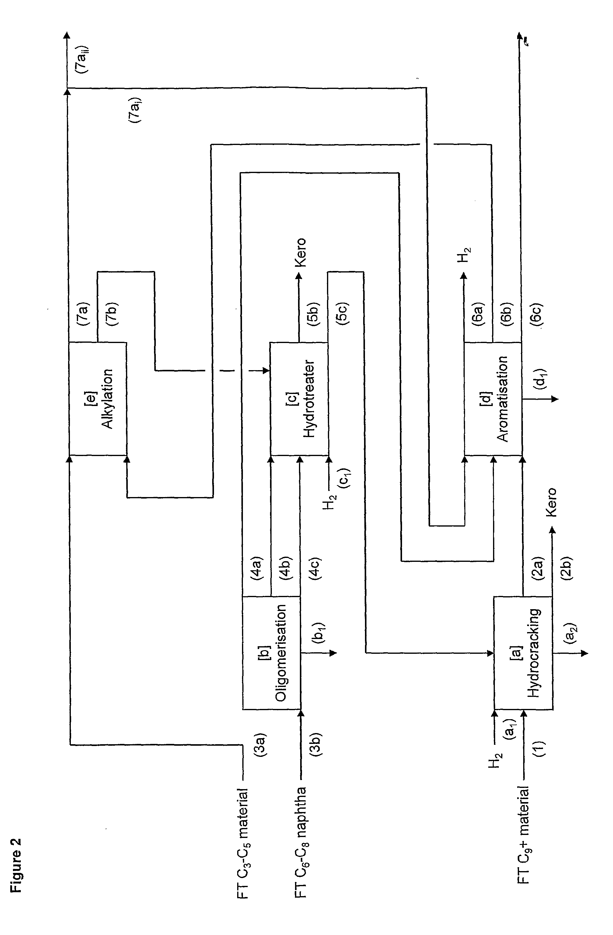
[0079]The jet fuel refinery design in this example as shown in FIG. 2 is based on the feed from a HTFT. The aim of this example is to show how much jet fuel can be produced from Fischer-Tropsch syncrude using the present invention.

[0080]The Fischer-Tropsch C9 and heavier syncrude (boiling point typically >130° C.) is used as feed stream 1 to the hydrocracker unit [a], which is operated in accordance with the description of this invention. The C16 and heavier distillate range product (boiling point typically >280° C.) from olefin oligomerisation stream 4c is first hydrotreated to produce stream 5c and then also hydrocracked. This results in the production of mainly kerosene stream 2b with a yield of around 75% on a fresh feed basis. The C3-C8 light hydrocarbons stream 2a are routed to the aromatisation unit [d].

[0081]Fischer-Tropsch C6-C8 syncrude (boiling range typically 40-130° C.) is used without pretreatment as feed stream 3b to the oligomerisation unit [b]. The oligomerisation p...

example 2

[0085]The jet fuel refinery design in this example and as shown in FIG. 3 is based on the same feed as Example 1. The difference lies in the selection of oligomerisation, aromatisation and alkylation processes. The aim of this example is to show that this invention is also capable of maximising jet fuel production, while meeting motor-gasoline specifications (Euro-4) for the naphtha. A further objective of this example is to illustrate how integration of the Fischer-Tropsch aqueous product work-up is beneficial.

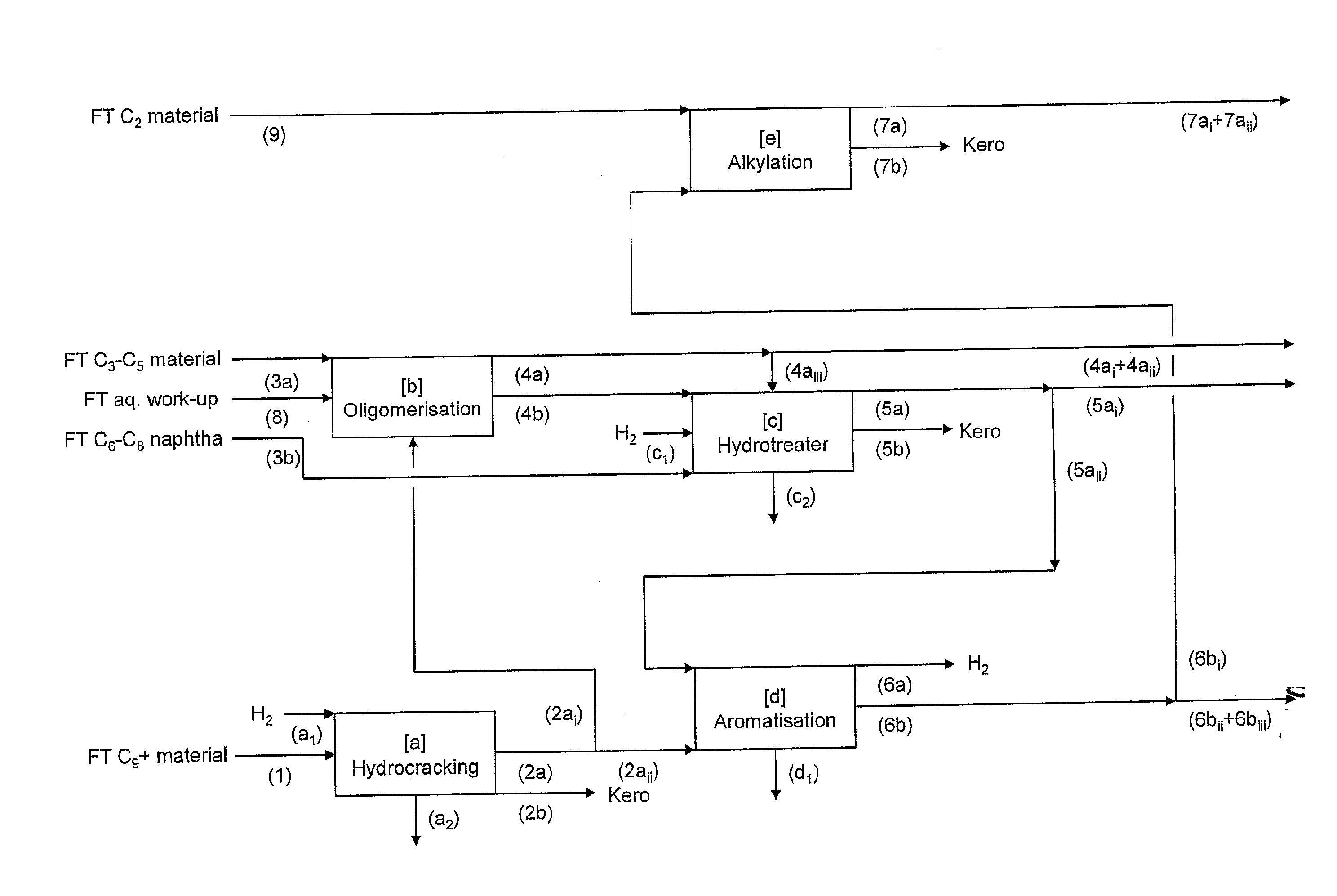
[0086]The hydrocracker unit [a], which is operated in accordance with this invention, converts the Fischer-Tropsch C9 and heavier syncrude stream 1 to kerosene stream 2b and lighter products stream 2a. Only the C6-C8 fraction stream 2aii is routed to the aromatisation unit [d], while the C3-C5 fraction stream 2ai is routed to the oligomerisation unit [b] to be used as diluent for heat management.

[0087]The oligomerisation and alkylation conversion is combined in a single unit ...

example 3

[0092]The jet fuel refinery design in Example 2 was modified by changing the way in which the aromatic alkylation is performed. In this example as shown in FIG. 4, a separate alkylation unit is used based on a zeolite catalyst, which is operated in such a way that the mono-alkylated aromatics are recycled to increase the yield of di-alkylated aromatics. Furthermore, ethylene has been selected as alkylating olefin to boost the overall yield of motor-gasoline and jet fuel on similar feed basis as Example 2, without significantly changing the motor-gasoline to jet fuel ratio.

[0093]The feeds, operation and products from the hydrocracker unit [a] is the same as in Example 2.

[0094]The oligomerisation unit [b], like in example 2, is based on a process using a SPA catalyst. The feeds are similar to that in Example 2, the only difference being that no aromatics are fed to this unit. The product is therefore not rich in alkyl aromatics, but consists mainly of aliphatic hydrocarbons. The produ...


PUM

PropertyMeasurementUnit
boilingaaaaaaaaaa

Abstract

The invention provides a Fischer-Tropsch jet fuel refining process which has a jet fuel yield in excess of 60% by mass, said process including at least four of the following five conversion processes: a. hydrocracking one or more of a FT kerosene and heavier material fraction and a C9 and heavier FT syncrude fraction; b. oligomerising an FT syncrude fraction including hydrocarbons in the range C2 to C8; c. hydrotreating one or more of an FT syncrude fraction, a product from process b., and an alkylated FT syncrude fraction; d. aromatizing one or more of an FT syncrude fraction including hydrocarbons in the range C2 to C8, a product from process a., a product from process b, a product from process c., and a product from an aromatic alkylation process; and e. alkylating one or more of an FT syncrude fraction including hydrocarbons in the C2 to C6 range, a product from process b., and a product from process d.

Description

FIELD OF THE INVENTION[0001]The invention relates to a process for the production of jet fuel from synthetic crude produced by a Fischer-Tropsch process.BACKGROUND OF THE INVENTION[0002]The Fischer-Tropsch (FT) synthesis has been used for long time for the production of synthetic hydrocarbons from synthesis gas (syngas), a mixture of gases comprising mostly hydrogen (H2) and carbon monoxide (CO).[0003]The FT synthesis is a chemical reaction conducted over a metal oxide catalyst where the active metal comprises iron (Fe), cobalt (Co), ruthenium (Ru) and nickel (Ni). These catalysts can be produced by precipitation or can be supported in a metal oxide like alumina, titania, zirconia, magnesia and the like.[0004]The FT synthesis primary reaction can be described as follows:2H2+CO→—[CH2]—+H2O[0005]In this reaction —[CH2]— represents the primary building block of a paraffinic hydrocarbon, sometimes also referred as alkanes.[0006]The process is carried out at elevated temperatures normall...

Claims


Application Information

Patent Timeline
Patent Type & Authority Applications(United States)
IPC IPC(8): C10G69/00
CPCC10G2/32C10G29/205C10G35/04C10G47/00C10G49/00C10G50/00C10G69/10C10G69/123C10G69/126C10G69/14C10G2300/4025C10G2300/1022C10G2400/08
Inventor DE KLERK, ARNO
Owner SASOL TEKHNOLODZHI PROPRIEHJTEHRI LTD
Why Eureka
Try Eureka