Battery and heat exchanger structure thereof

a heat exchanger and battery technology, applied in the direction of nickel accumulators, cell components, sustainable manufacturing/processing, etc., can solve the problems of difficult to keep electrolytic solutions inside the separator, and inability to keep enough oxygen-permeating functions, etc., to achieve the effect of reducing production costs, avoiding short-lived battery life, and improving durability

Inactive Publication Date: 2010-05-06
KAWASAKI HEAVY IND LTD
View PDF11 Cites 5 Cited by
  • Summary
  • Abstract
  • Description
  • Claims
  • Application Information

AI Technical Summary

Benefits of technology

[0034]In accordance with the inventions set forth in claims 1, 3, 4 and 9, electrolytic solution requirements can be filled in a vessel and a separator is made of a hydrophobic material. Accordingly, since oxygen gas generated at the cathode by a cell reaction permeates smoothly through the separator, solution-keeping function and oxygen-permeating function can be obtained. Since electrolytic solution requirement is filled in the vessel, a life of battery does not get short and durability can be improved. Furthermore, since a hydrophilic treatment is unnecessary, a production cost can be kept down. Besides, it is possible to improve energy density and realize maintenance free.
[0035]In accordance with the inventions set forth in claims 2 and 5, the following effects can be obtained. Since activity of anode comprising hydrogen occluding alloy is remarkably inferior in early electrochemical reaction, the discharge capacity is small for several cycles after the beginning of the cell reaction and surplus hydrogen is accumulated at the anode in the early activating process of repeating charging and discharging by ten and several cycles. Accordingly, if oxygen is supplied from a source of oxygen supply to the anode vessel, the oxygen is reacted with surplus hydrogen in the anode to be converted to water. If oxygen is supplied to the cathode vessel, the oxygen permeates through the separator to react with surplus hydrogen in the anode to be converted to water. When the need arises, if oxygen is supplied from a source of oxygen supply to the anode vessel and the cathode vessel, the oxygen can be reacted with surplus hydrogen in the anode to be converted to water.
[0036]In accordance with the inventions set forth in claims 3, 4, 6, 7 and 8, since a temperature of the battery can be maintained within the appropriate range by a medium for transmitting heat which is carrying along a carrying route, deterioration of the battery is not going ahead and the cell reaction can be conducted smoothly.

Problems solved by technology

Because, if the site of gaps between fibers constituting the separator gets larger and the number of the gaps get smaller, the oxygen gas permeates easily through the separator but it is difficult to keep the electrolytic solution inside the separator.
As a result, a course of oxygen for permeation is taken away and it is not possible to keep enough oxygen-permeating function.
But, if the quantity of the electrolytic solution is small, it leads to dry-out (drying up) and a short life of the battery.
Therefore, it is difficult to keep the hydrophobic portion because the hydrophilic resin is impregnated underneath the coating layer of the hydrophobic resin.
But, since the opening has a diameter of 6 mm and the opening is large, it is very difficult to provide many hydrophobic portions such that each hydrophobic portion has small area.
However, it is difficult to realize it according to the separators set forth in patent references No. 1 and 2.
It is troublesome to divide correctly the separator into fine hydrophilic portion and fine hydrophobic portion.
The cost of production is extremely increased.
However, even if the anode is larger than the cathode, the internal pressure of the anode is going up due to the accumulated hydrogen and it causes the damage for the anode.
However, the heat exchanger structure of the battery which can achieve the above object has not been proposed as yet.

Method used


Image

  • Battery and heat exchanger structure thereof
  • Battery and heat exchanger structure thereof
  • Battery and heat exchanger structure thereof

Examples


first embodiment

OF HEAT EXCHANGER STRUCTURE OF BATTERY

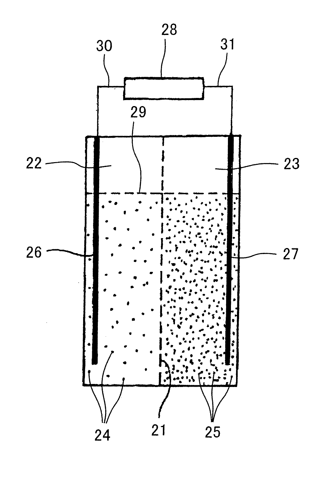
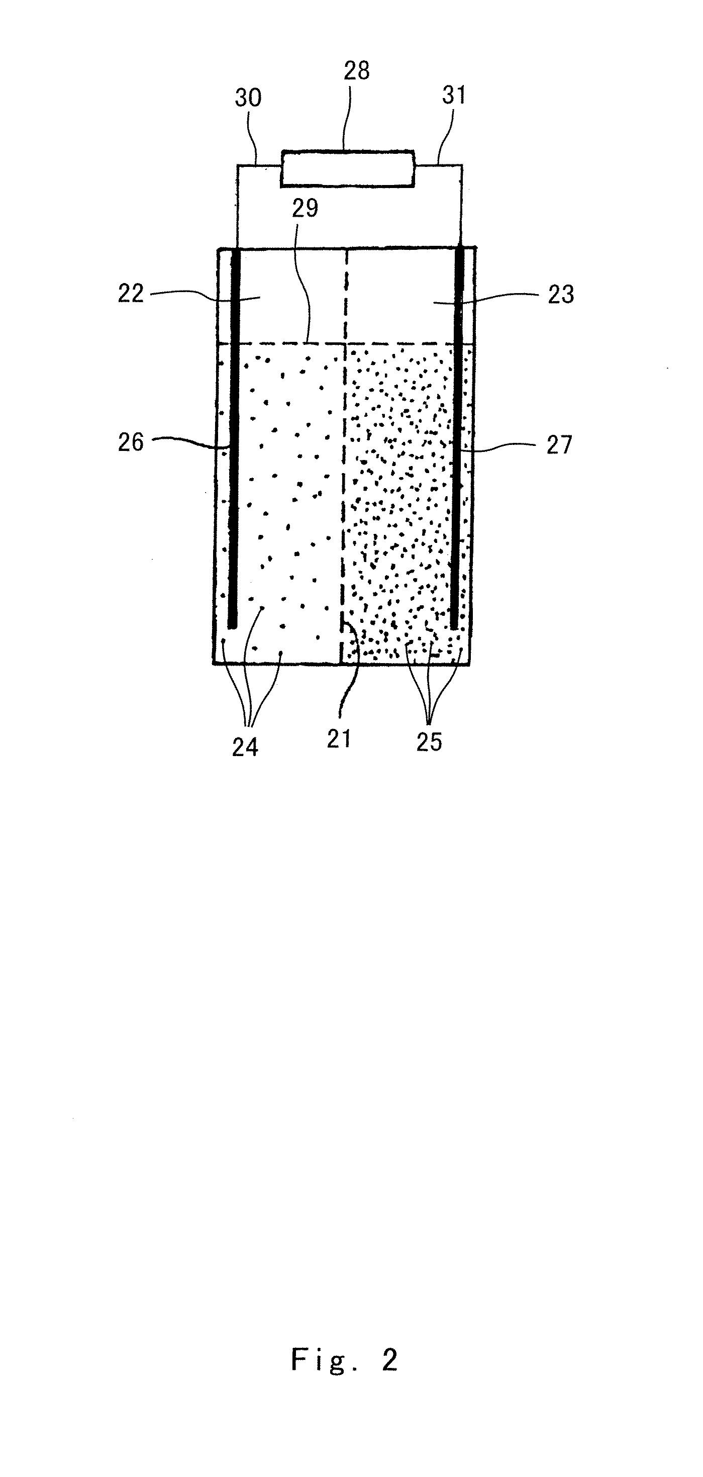
[0155]As described above, heat is generated due to a cell reaction in the battery. Particularly, in accordance with the airtight type battery, a person skilled in the art cannot think little of heat generated by the cell reaction. Accordingly, the airtight type battery is preferably provided with heat exchanger structure.

[0156]The conventional cylindrical battery or cubic battery or rectangular parallel-piped battery have a cooling structure that the outside of the battery casing is cooled. Therefore, it is difficult to attain the fixed cooling effect. Because in any of the cylindrical battery, cubic battery or rectangular parallel-piped battery, the direction for transmitting heat is perpendicular to the location of electrodes in the disposed direction of the separator and the active material. For example, in case of cylindrical battery, the heat shall be transmitted to the radius direction. In short, it is necessary to transmit heat to the out...

second embodiment

OF HEAT EXCHANGER STRUCTURE OF BATTERY

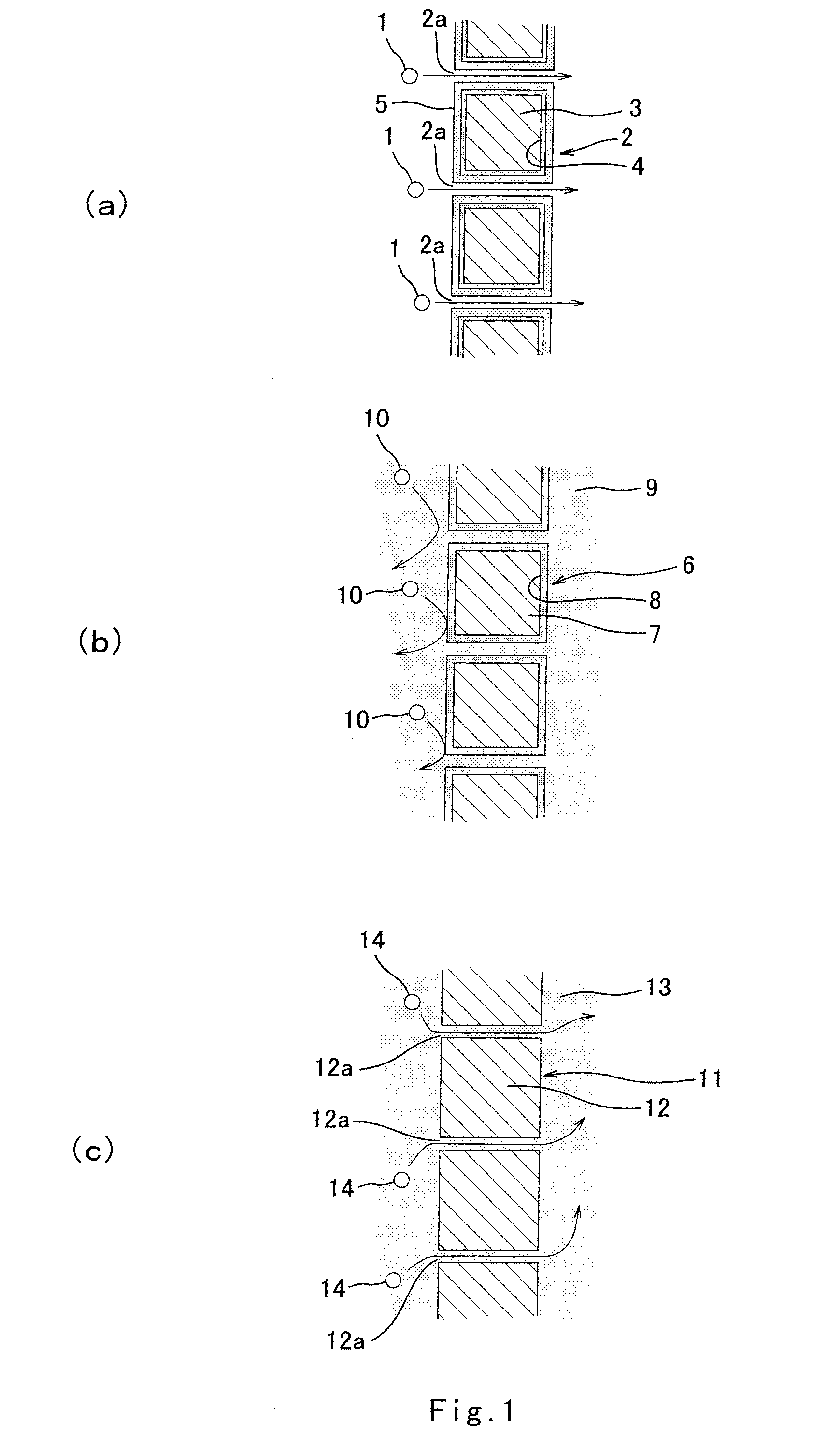
[0163]FIG. 6 is a perspective view showing a battery unit multilayer 81 with a heat exchanger structure of the present invention which is cooled by a fan and a wind tunnel (air carrying space). The battery unit multilayer 81 has an air carrying space 82 for carrying air in the lower part. Air inhaled by air intake fans 83a and 83b is emitted to the outside from an air carrying space 84 in the upper part through the air carrying space 82 and heat transmitting space inside the battery unit multilayer 81. The arrow of FIG. 6 denotes a direction of air ventilation.

[0164]FIG. 7(a) is a view showing longitudinal section of one example of a battery unit multilayer with a heat exchanger structure. A battery unit multilayer 81a has a configuration which consists of six battery units layered one upon the other. Each battery unit has the following constitution: An electrolytic solution is filled between a cathode plate 85 and an anode plate 83. A separator...

third embodiment

OF HEAT EXCHANGER STRUCTURE OF BATTERY

[0169]FIG. 8 is a perspective view showing one example of a heat exchanger plate 96. The heat exchanger plate 96 is made of nickel-plated aluminum. Many air carrying spaces 97 are provided in the vertical direction. In FIG. 7, the heat exchanger plate 96 may be interposed between the cathode plate 85 and the anode plate 86, and air inhaled by intake fans 83a and 83b can be carried through air carrying space 97. The heat exchanger plate is in contact with both of the cathode plate and the anode plate, and the cathode plate is connected to the anode plate by the heat exchanger plate. Therefore, the heat exchanger plate has preferably a good electrical conductivity. Aluminum has a relatively low electrical resistance and a relatively high heat conductivity. And so, aluminum has the properties suitable for the heat exchanger plate of the present invention. But aluminum has a disadvantage to be liable to be oxidized. If an aluminum plate is nickel-pl...


PUM

PropertyMeasurementUnit
diameteraaaaaaaaaa
temperatureaaaaaaaaaa
internal pressureaaaaaaaaaa

Abstract

The object of the invention is to provide a battery which has a simple structure with good durability and can continue a cell reaction smoothly. Two vessels are connected with a hydrophobic ion-permeable separator 21 interposed therebetween. An electrolytic solution comprising, an anode active material is filled in an anode vessel 22, and an electrolytic solution comprising a cathode active material is filled in a cathode vessel 23. An electrically conductive anode current collector 26 is in contact with the anode powdered active material in the anode vessel 22, and an electrically conductive cathode current collector 27 is in contact with the cathode powdered active material in the cathode vessel 23.

Description

TECHNICAL FIELD[0001]The present invention relates to a battery and a heat exchanger structure thereof.BACKGROUND ART[0002]Recently, the pursuit of higher quality such as good performance, high safety, long term quality guaranteed and the like is strongly made to an alkali battery which is used as portable use, mobile use, fixed use and the like. Particularly, a high power is demanded to a hybrid car which draws attention of the general public, a power tool and the like. It is requested that the alkali battery which is applied to such apparatuses shall be provided with high power and high energy density. Particularly, a nickel hydrogen battery is a secondary battery which is provided with a cathode comprising nickel hydroxide as main active material and an anode comprising hydrogen occluding alloy as main active material. Since the nickel hydrogen battery has high energy density and high reliability, it has come rapidly into wide use.[0003]Well, the battery's performance is certainl...

Claims


Application Information

Patent Timeline
Patent Type & Authority Applications(United States)
IPC IPC(8): H01M10/50H01M2/16H01M10/30H01M10/52H01M10/60H01M10/623H01M10/6235H01M10/625H01M10/647H01M10/653H01M10/6551H01M10/6555H01M10/6557H01M10/6563H01M10/6568H01M10/658H01M50/409H01M50/489
CPCH01M2/16H01M10/04H01M10/24H01M10/34H01M10/281H01M10/625H01M10/6563H01M10/647H01M10/6557H01M10/6567H01M10/613Y02E60/10H01M50/409Y02P70/50H01M50/489H01M10/345H01M10/30
Inventor TSUTSUMI, KAZUONISHIMURA, KAZUYA
Owner KAWASAKI HEAVY IND LTD
Why Eureka
Try Eureka