Fluid separation structure and a method of manufacturing a fluid separation structure

a technology of fluid separation and structure, which is applied in the direction of electrolysis, chemical vapor deposition coating, diaphragms, etc., can solve the problems of inability to ensure the quality and reproducibility of manufactured devices, difficult to manufacture such devices on an industrial scale, and difficult to meet the requirements of the requirements of the industrial scale. achieve the effect of improving the device performance, high performance and refinement of the spatial resolution of the nanowire array

Active Publication Date: 2010-05-13
NXP BV
View PDF8 Cites 9 Cited by
  • Summary
  • Abstract
  • Description
  • Claims
  • Application Information

AI Technical Summary

Benefits of technology

[0024]According to an exemplary embodiment of the invention, a final coating of the pillar shaped semiconductor region (micropillars) may be performed with any desirable materials that present hydrophobic or hydrophilic properties that can be tailored to increase the device performance. Furthermore, patterning the surface is possible, wherein such a patterning may particularly allow defining hydrophobic and hydrophilic regions, thereby defining a route of the molecules along a surface of the fluid separation structure. Thus, a high performance medical device for molecular medicine applications may be provided.
[0025]According to an exemplary embodiment, a manufacturing method for a patterned device for separating DNA is provided. Nanowires may be grown on a substrate, a silicon oxide structure may be deposited on the nanowires, and the silicon oxide may be removed from the tip of the nanowires to expose an upper end portion of the nanowires. The remaining portion of the silicon oxide structure may serve as a mechanical reinforcement for the sensitive nanowires, whereas the exposure of the tip may refine the spatial resolution of the nanowire array.
[0026]The provision of nanowires such as nanotubes may allow improving the robustness of the separation web as compared to molding or lithographical post generation, since grown nanowires have specifically strong intrinsic chemical binding properties. In contrast to approaches in which pillars are fabricated using a replica molding method, the nanowire growing technique according to an exemplary embodiment of the invention may allow preventing a rapid degradation of the quality of the structure, and may guarantee a regular patterning. More particularly, the micropillars and possible microfluidic channels may be fabricated directly on a silicon wafer without the need of fabricating a molding first. This may allow for an exact control of the dimension due to the fact that no degradation of the microstructure is produced. In contrast to conventional molding fabrication techniques which do not enable a pos

Problems solved by technology

Conventional separation approaches such as gel electrophoresis or capillary electrophoresis become problematic when being applied to very small volumes of a biological sample.
However, a sufficient quality and reproducibility of the manufactured devic

Method used


Image

  • Fluid separation structure and a method of manufacturing a fluid separation structure
  • Fluid separation structure and a method of manufacturing a fluid separation structure
  • Fluid separation structure and a method of manufacturing a fluid separation structure

Examples


Embodiment Construction

[0058]The illustration in the drawing is schematical. In different drawings, similar or identical elements are provided with the same reference signs.

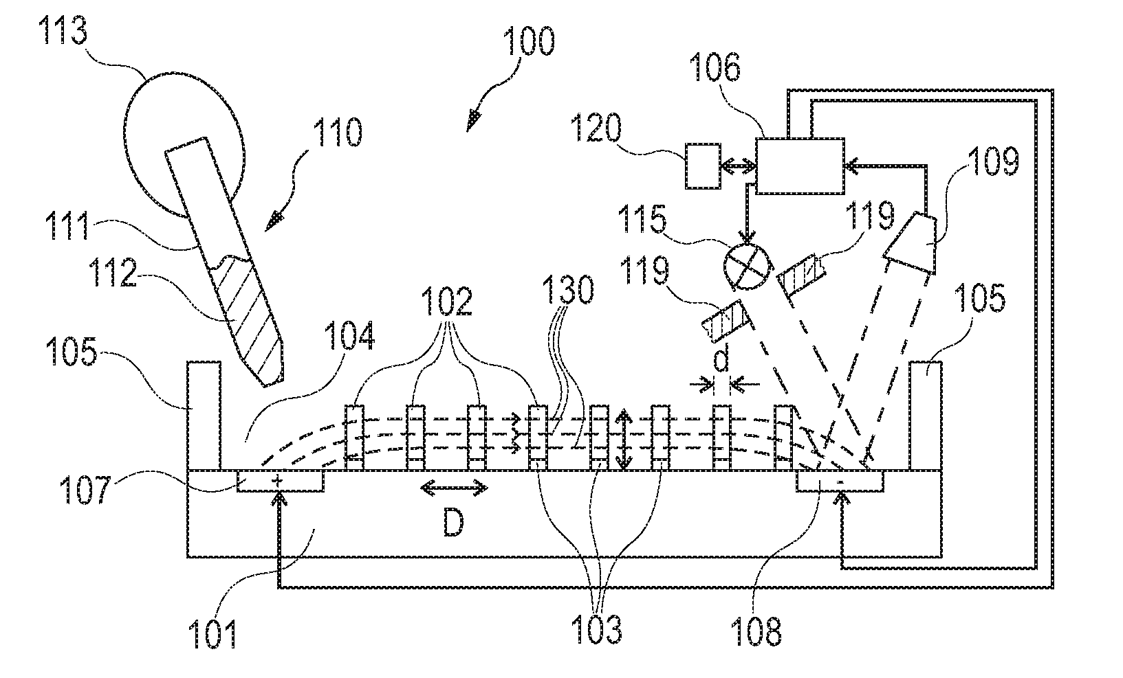
[0059]In the following, referring to FIG. 1, a fluid separation apparatus 100 according to an exemplary embodiment of the invention will be explained.

[0060]The fluid separation apparatus 100 comprises a silicon substrate 101 such as a silicon wafer. A plurality of nanowires 102 are vertically grown in rows and columns, that is to say in a two-dimensional configuration, on a surface of the substrate 101, more particularly on catalyst spots 103 which have previously been formed by a deposition technique on a surface of the substrate 101.

[0061]As can be taken from FIG. 1, a sample reservoir 104 is defined by the main surface of the substrate 101 as well as by lateral sidewalls 105 delimiting the structure.

[0062]FIG. 1 schematically illustrates a pipette 110 having a capillary 111 and a fluidic sample 112 filled in the capillary 111. By ma...


PUM

PropertyMeasurementUnit
Fractionaaaaaaaaaa
Distanceaaaaaaaaaa
Distanceaaaaaaaaaa

Abstract

An electrophoretic fluid separation structure (100) comprising a substrate (101) and a plurality of vertical nanowires (102) grown on the substrate (101).

Description

FIELD OF THE INVENTION[0001]The invention relates to a fluid separation structure.[0002]Moreover, the invention relates to a method of manufacturing a fluid separation structure.[0003]Beyond this, the invention relates to a method of using a fluid separation structure for separating components of a fluidic sample.BACKGROUND OF THE INVENTION[0004]Separation of components (such as biomolecules, for instance DNA) of a fluidic sample becomes more and more important for medical applications, biochemistry, food chemistry, etc.[0005]Conventional separation approaches such as gel electrophoresis or capillary electrophoresis become problematic when being applied to very small volumes of a biological sample.[0006]Ken-ichi Inatomi et al. (2003) “Electrophoresis of DNA in micro-pillars fabricated in polydimethylsiloxane”, Microelectronic Engineering, Volume 70, Issue 1, pages 13 to 18 discloses the fabrication of a device containing micro-pillars for separation of DNA. It is made of polydimethy...

Claims


Application Information

Patent Timeline
IPC IPC(8): G01N27/447B81B7/00G01N21/64B05D5/00B81C1/00
CPCG01N27/44747G01N27/44791Y10T137/2224Y10T137/7976
Inventor GARCIA TELLO, PABLOMADAKASIRA, VIJARAGHAVAN
Owner NXP BV
Why Eureka
Try Eureka