Antenna multiplexing system and method of smart antenna and multiple-input multiple-output antenna

a smart antenna and multiplexing technology, applied in diversity/multi-antenna systems, multi-frequency code systems, digital transmission, etc., can solve the problems of weak coverage capability of the common channel and insufficient advantages of the smart antenna performance, and achieve the effect of increasing throughpu

Active Publication Date: 2010-06-03
CHINA MOBILE COMM GRP CO LTD
View PDF10 Cites 51 Cited by
  • Summary
  • Abstract
  • Description
  • Claims
  • Application Information

AI Technical Summary

Benefits of technology

[0004]An object of an embodiment of the present invention is to provide an antenna multiplexing system and method of a smart antenna and a Multiple-Input Multiple-Output antenna, which, by the organic combination of the smart antenna and the Multiple-Input Multiple-Output antenna, achieves common presence and common use of the smart antenna and the MIMO antenna in a system. The unbalance between the coverage capabili

Problems solved by technology

However, since a common channel and a broadcast channel (or a MBMS service) do not have a downlink beam forming gain, there is a significant difference between the coverage capability of the common channel and the broadcast channel (or the MBMS service) and that of a channel for a general service, so that the actual coverage range of the network or the MBMS service is smaller than that of a service

Method used


Image

  • Antenna multiplexing system and method of smart antenna and multiple-input multiple-output antenna
  • Antenna multiplexing system and method of smart antenna and multiple-input multiple-output antenna
  • Antenna multiplexing system and method of smart antenna and multiple-input multiple-output antenna

Examples


first embodiment

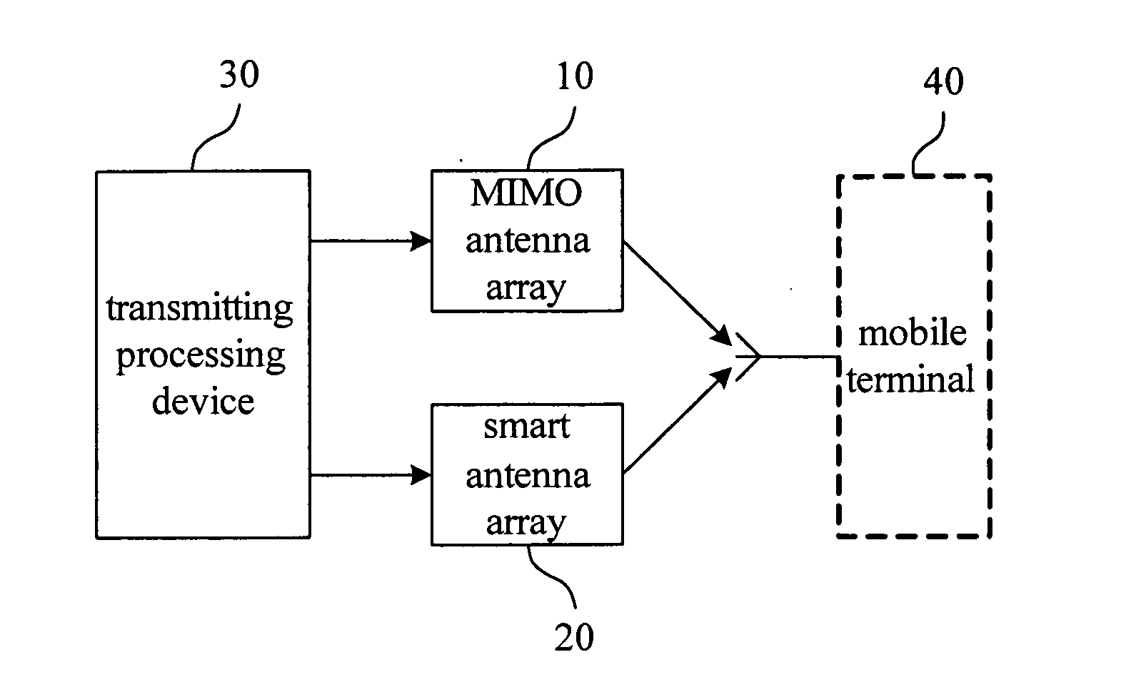
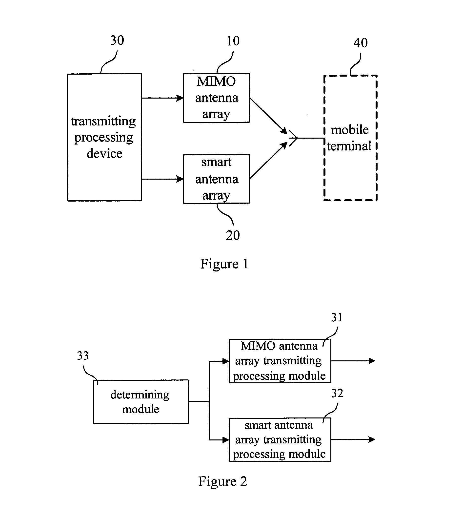
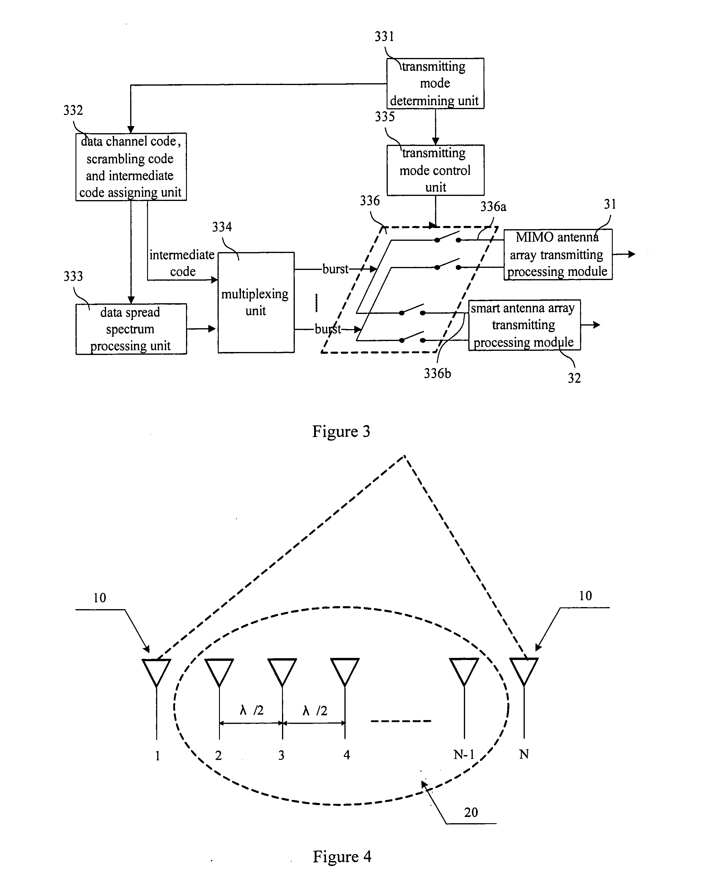
[0063]FIGS. 4 and 5 are schematic diagrams of structures of the first embodiment of the embodiments of the present invention. As shown in FIG. 4, the first embodiment is an improvement on the basis of the smart antenna array used in the TD-SCDMA system. The number of the antenna elements is N. The antenna elements are divided into two groups, one of which consists of two antenna elements located at two end portions and is served as a MIMO antenna array 10, and the other of which consists of N−2 antenna elements in the middle and is served as a directional smart antenna array, wherein N is an integer. The MIMO antenna array 10 and the smart antenna array 20 both are vertically polarized antenna arrays.

[0064]Since spacing of the antenna elements of the smart antenna array used in the TD-SCDMA system is smaller than or equal to λ / 2, all N antenna elements satisfy the requirement of the smart antenna and may be used to perform beam forming. On the other hand, two antenna elements locate...

second embodiment

[0066]FIGS. 6 and 7 are schematic diagrams of structures of the second embodiment of the embodiments of the present invention, which are an improvement of the structure of the first embodiment. Two antenna elements of the MIMO antenna array 10 in FIG. 6 are located at two end portions, and two antenna elements of the MIMO antenna array 10 in FIG. 7 both are located at the same end portion. As shown in FIGS. 6 and 7, the MIMO antenna array 10 of the second embodiment consists of an antenna element 11 and an antenna element 12 located at the far end(s), and the smart antenna array 20 consists of the remaining N−2 antenna elements. The antenna element 11 and the antenna element 12, which are orthogonally polarized, are dual-polarized antennas. The smart antenna array 20 is vertically polarized antenna array.

[0067]In the smart antenna array used in the existing TD-SCDMA system, due to the influence of factors such as size, scale and distance of antenna elements and antenna element spaci...

third embodiment

[0068]FIG. 8 is a schematic diagram of a structure of the third embodiment of the embodiments of the present invention. As shown in FIG. 8, the third embodiment is still based on the smart antenna array used in the TD-SCDMA system. The number of the antenna elements, that is, N, is kept constant. A first antenna element group 13 at one far end and a second antenna element group 14 at the other far end constitute the MIMO antenna array. N−4 antenna elements in the middle constitute the directional smart antenna array 20. The spacing of two antenna elements in the first antenna element group 13 and the second antenna element group 14 should satisfy the requirement of dependence of the MIMO application, and the spacing of the N−4 antenna elements in the middle should be smaller than or equal to λ / 2 to satisfy the requirement of application of the smart antenna. The antenna elements in the first antenna element group 13, the second antenna element group 14 and the smart antenna array 20...


PUM


Abstract

An antenna multiplexing system and a method of a smart antenna and a Multiple-Input Multiple-Output antenna are provided, wherein the system includes a MIMO antenna array and a smart antenna array, the smart antenna array includes several groups of antenna array elements in which the distance between neighbor antenna array elements is less than or equal to one half of wavelength, and the smart antenna array comprises at least two groups of antenna array elements with the coherence sufficient for the requirement of the MIMO applications. The method includes: in accordance with the type of the data to be transmitted, determining a transmitting mode and processing the data to be transmitted accordingly, and in accordance with the transmitting mode, controlling the MIMO antenna array or smart antenna array, so as to transmitting the data to the mobile terminal. With the premise that the actual coverage of TD-SCDMA system should be further improved, the requirement of higher user throughout could be met, and the MIMO antenna system could satisfy the requirement of the future system evolution. Both of the applications of the MIMO and the smart antenna could be met with the use of the same antenna feeding system, and the adaptive switching of the MIMO and the smart antenna with respect to the user could be achieved.

Description

FIELD OF THE INVENTION[0001]The present invention relates to a multiple antenna system and method, particularly to an antenna multiplexing system and method of a smart antenna and a Multiple-Input Multiple-Output antenna.BACKGROUND OF THE INVENTION[0002]The current multiple antenna technique mainly includes two forms: a smart antenna system, and a Multiple-Input Multiple-Output (MIMO) antenna system. In the MIMO antenna system, multiple antennas are used to suppress channel fading or to improve channel capacity, which may provide spatial multiplexing gain and spatial diversity gain for the system, wherein spatial multiplexing technology may greatly improve the channel capacity and spatial diversity may increase reliability of a channel and decrease bit error rate of the channel. The MIMO antenna system mainly achieves diversity gain dependent upon independence of spatial channel fading characteristics on different antenna pairs. Therefore, larger antenna element spacing is needed in...

Claims


Application Information

Patent Timeline
IPC IPC(8): H04K1/10
CPCH04B7/0413H04B7/0469H04B7/0691H04B7/0689
Inventor XU, XIAODONGLIU, GUANGYICHENG, GUANGHUIHUANG, YUHONGYAN, ZHIGANGCUI, CHUNFENG
Owner CHINA MOBILE COMM GRP CO LTD
Why Eureka
Try Eureka