
Thermoelectric material and method of manufacturing the material

a technology of thermoelectric materials and manufacturing methods, which is applied in the direction of thermoelectric device junction materials, thermoelectric devices, electrical apparatus, etc., can solve the problems of compound semiconductors containing large amounts of expensive ge, compound semiconductors with limits in reachable merit figures, etc., and achieve rapid solidification, reduce thermal conductivity , increase the power factor pf

Active Publication Date: 2010-06-17
TOYOTA CENT RES & DEV LAB INC
View PDF0 Cites 21 Cited by
  • Summary
  • Abstract
  • Description
  • Claims
  • Application Information

AI Technical Summary

Benefits of technology

The present invention provides a thermoelectric material with reduced thermal conductivity without the use of expensive elements such as Zr or Hf, and a method of manufacturing the material. The material contains a half-Heusler compound with specific compositions that reduce the amount of secondary phases that can deteriorate the thermoelectric property. The material also has a low amount of Hf substitution at the Ti sites and a high power factor PF. The method of manufacturing involves rapid cooling of a molten metal. The invention also provides a method of optimizing the composition and manufacturing conditions to further improve the thermoelectric properties of the material.

Problems solved by technology

Among them, the Bi—Te and Pb—Te based compound semiconductors exhibit high ZT in the low temperature range; however, there is a problem in that the semiconductors cannot be used in the intermediate to high temperature range, and that the semiconductors contain large amounts of elements having large environmental burdens, such as Pb, Te and Sb.
Further, the Ge—Si based compound semiconductors contain large amounts of expensive Ge.
However, there is a problem in that many of the skutterudite compounds exhibiting high thermoelectric properties in the low to intermediate temperature range contain large amounts of elements having large environmental burdens such as Sb.
Although both the TiNiSn compounds and the ZrNiSn compounds essentially have high power factors, there is a problem in that those compounds have limits in reachable figures of merit due to their high thermal conductivities.
The TiNiSn based compound has a relatively high power factor PF; however, there is a problem in that the thermal conductivity κ is high.
However, heavy elements such as Zr and Hf (in particular, Hf) are expensive in comparison with Ti, causing a problem in terms of cost.
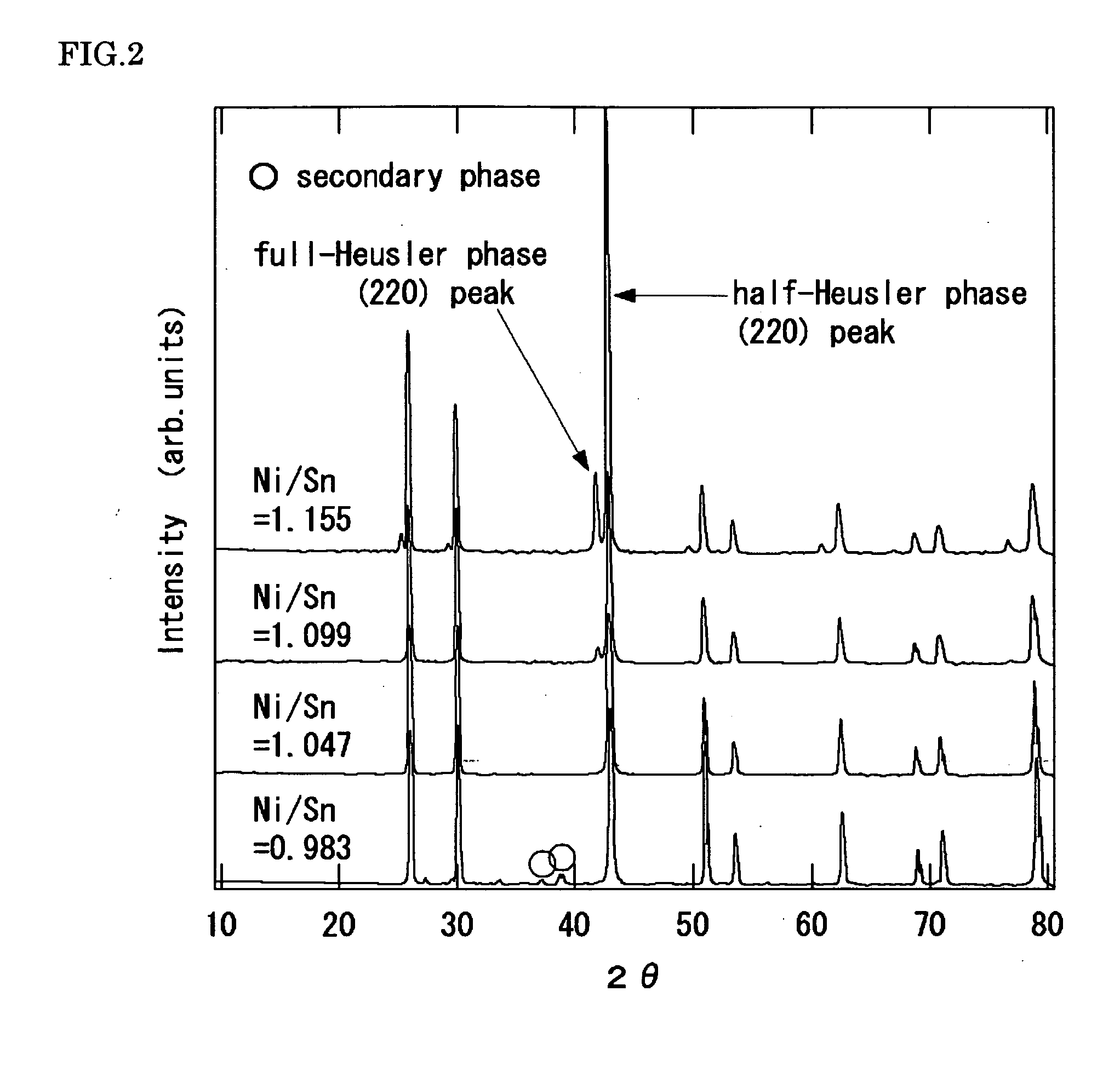
If the secondary phase is a metallic phase, precipitation of the secondary phase may cause the thermoelectric property thereof to be deteriorated.

Method used


Image

  • Thermoelectric material and method of manufacturing the material
  • Thermoelectric material and method of manufacturing the material
  • Thermoelectric material and method of manufacturing the material

Examples


example 1

1. Production of Samples

[0198]Ti (purity: 99.9% or more), Ni (purity: 99.9%) and Sn (purity: 99.9% or more) were weighed such that their feed values could produce Ti1−αNi1−αSn (−0.05≦α≦0.05) or TiNi1+βSn (−0.01≦β≦0.03). These were placed into a crucible made of boron nitride, and then placed in a high frequency induction furnace. After evacuating the inside of the furnace to 10−3 Pa range, Ar gas was introduced until the internal pressure within the chamber was raised to 0.34×10⁵ Pa. Subsequently, high frequency current was applied to a coil such that the raw material in the crucible was melted. After the material was melted, the resultant molten metal was furnace cooled to obtain an ingot.

[0199]The resultant ingot was remelted within a pipe made of boron nitride, and then the molten metal was rapidly cooled on a Cu roll surface rotating at 3000 rpm to obtain a ribbon-shaped sample. The sample was ground and then sintered under a pressure of 50 MPa at 1100° C.×15 minutes by using a ...

example 2

1. Production of Samples

[0214]In order to substitute the relevant sites of the sample 6 of Example 1 as a base material, the following weighing was performed:

(1) The Sn sites thereof were to be substituted with Sb (up to 1%);

(2) The Ni sites thereof were to be substituted with Cu (up to 0.5%); or

(3) The Sn sites thereof were to be substituted with Sb, and the Ti sites thereof was to be substituted with Y whose amount was the same as that of Sb (up to 3%). The purities of Sb, Cu and Y thus used are 99.9% or more, respectively.

[0215]These substances were placed in a crucible made of boron nitride, and then placed in a high frequency induction furnace. After evacuating the inside of the furnace to 10−3 Pa range, Ar gas was introduced until the internal pressure within the chamber was raised to 0.34×10⁵ Pa. Subsequently, high frequency current was applied to a coil such that the raw material in the crucible was melted. After the material was melted, the resultant molten metal was furnac...

example 11

1. Production of Samples

[0221]Zr, Ni and Sn were weighed such that the whole composition of them was to become ZrNi1+ySn (0≦y≦0.10), and then they were melted by high frequency induction heating with the use of a crucible made of boron nitride.

[0222]The resultant ingot was remelted by high frequency induction heating, and the molten melt was rapidly cooled on a Cu roll surface rotating at 3000 rpm to obtain a ribbon-shaped sample. The sample was ground and then sintered under a pressure of 50 MPa at 1100° C.×15 minutes by using a spark plasma sintering apparatus.

2. Test Method

[2.1. Powder X-ray Diffraction]

[0223]The resultant sintered body was ground such that X-ray diffraction patterns were measured.

[2.2. Thermoelectric Property]

[0224]Samples were cut out of the sintered body such that the Seebeck coefficient S, electrical conductivity σ and thermal conductivity κ were measured. The power factor PF and dimensionless figure of merit ZT were calculated by using the measured Seebeck c...


PUM

PropertyMeasurementUnit
lattice constantaaaaaaaaaa
temperatureaaaaaaaaaa

Abstract

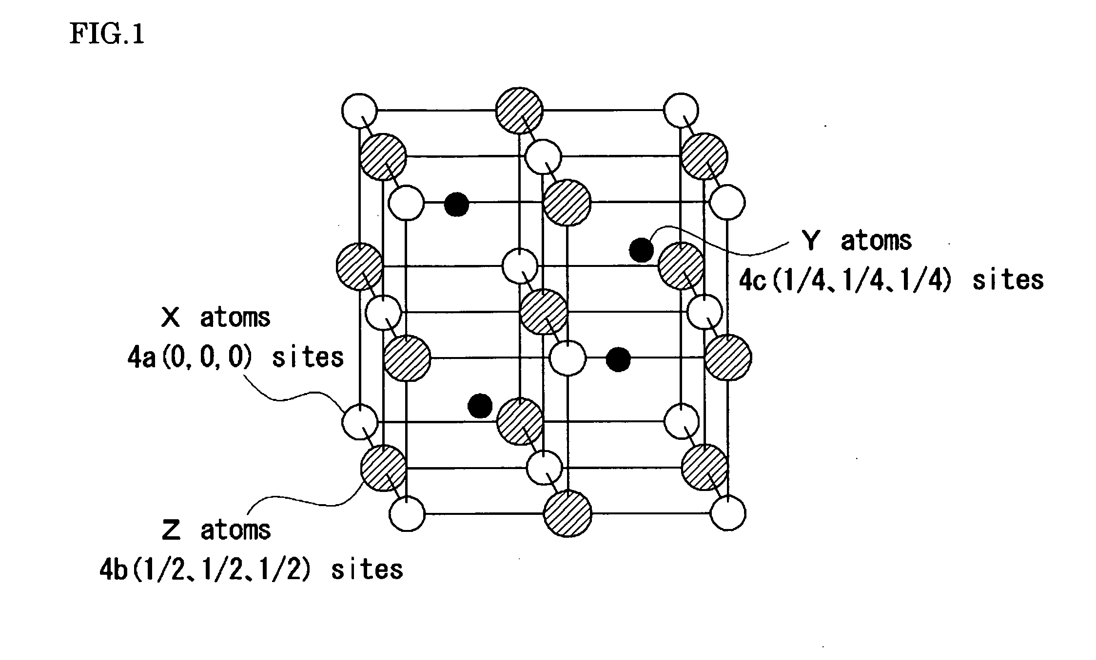
The present invention provides a thermoelectric material and a method of manufacturing it. The thermoelectric material contains a half-Heusler compound including a composition represented by: (Ti1-aAa)1+x(Ni1-bBb)1+y(Sn1-cCc) where 0≦a<0.1, 0≦b<0.1 and 0≦c<0.1; −0.1≦x≦0.2 and 0<y≦0.2; A is one or more elements selected from the group consisting of group IIIa elements, group IVa elements (excluding Ti), group Va elements and rare earth elements; B is one or more elements selected from the group consisting of group VIIIa elements (excluding Ni) and group Ib elements; and C is one or more elements selected from the group consisting of group IIIb elements, group IVb elements (excluding Sn) and group Vb elements, wherein amounts of Zr substitution and Hf substitution at Ti sites of the half-Heusler compound are less than 1 at %, respectively.

Description

BACKGROUND OF THE INVENTION[0001]1. Field of the Invention[0002]The present invention relates to a thermoelectric material and a method of manufacturing the material, and more specifically, to a thermoelectric material containing a half-Heusler compound as a major component, and a method of manufacturing the material.[0003]2. Description of the Related Art[0004]Thermoelectric conversion refers to direct conversion of electric energies into thermal energies for cooling or heating with the use of the Seebeck effect or the Peltier effect, and vice versa. The thermoelectric conversion has the following characteristics:(1) Extra waste materials are not discharged during the energy conversion;(2) Exhaust heat can be effectively used;(3) Electric power generation can be continued until constituent materials are deteriorated; and(4) A movable device such as a motor or turbine is not necessary, and hence maintenance is not needed. Therefore, the thermoelectric conversion attracts attention a...

Claims


Application Information

Patent Timeline
Patent Type & Authority Applications(United States)
IPC IPC(8): H01L35/20C22F1/08
CPCB22F9/08H01L35/20C22C1/0483H10N10/854
Inventor MATSUBARA, MASATOHAZAMA, HIROFUMIASAHI, RYOJI
Owner TOYOTA CENT RES & DEV LAB INC
Learn More