A common problem in many different fields is the need to know the height of a liquid within a tank.
However, there are number of technical problems that have limited the usefulness of TDR to measurement of
liquid height within a tank.
In particular, such technical problems have prevented accurate and reliable detection of interfaces between
layers of comparatively similar dielectric constant, such as air and
hydrocarbon fuel, or between layers of stratified immiscible liquids.
One such technical problem is the effect of
relative permittivity (also referred to herein as “dielectric constant,” sometimes abbreviated as “dielectric”) on velocity of propagation.
Another such technical problem is the practical difficulty, using commercially available
electronics, of measuring the impedance changes that occur along the length of the TDR probe to a spatial resolution that will provide an acceptable rendering of the height profile of the various layers in which the TDR probe is immersed within the tank.
Resolving such impedance changes to a degree sufficient to accurately determine layer height will be especially difficult for interfaces between layers of comparatively similar dielectric constant.
That is, whereas it may have conventionally been possible to resolve interfaces between layers of comparatively dissimilar dielectric constant, such as air and water, it has conventionally been difficult to accurately resolve interfaces between layers of comparatively similar dielectric constant, such as air and
hydrocarbon fuel, or between layers of stratified immiscible liquids.
Thus, although it might be possible to capture, in analog fashion after the fashion of an
oscilloscope trace, the reflected waveform from a single interrogation pulse and observe such
picosecond-order impedance variations, it would be impractical to design
digital circuitry capable of capturing and
processing samples spaced apart at such small time increments over the course of a single interrogation
pulse cycle.
However, even with such techniques, the limitations of economically available electronics still make it impractical conventionally to spatially resolve the height profile of the various layers in which the TDR probe is immersed.
For this and other reasons, conventional commercial TDR systems have generally been unable to adequately resolve the impedance changes occurring along the length of the TDR probe with a spatial resolution and
response time sufficient to obtain a reasonably accurate rendering of the height profile of the various layers in which the TDR probe is immersed within the tank.
Several practical TDR systems have therefore been proposed to overcome these difficulties, but conventional TDR systems for measuring liquid level within a tank still suffer from problems such as inadequate resolution,
slow response time, and sensitivity to variation in dielectric constant and / or temperature.
However, because the pulse reflected from the probe bottom (which is typically in the vicinity of the tank bottom) must necessarily pass through the
liquid layer being measured, such measurements based on the
time of flight of the pulse reflected from the probe bottom are susceptible to variations in the temperature and dielectric constant of that
liquid layer.
In practice, however, it is found that the comparatively weak reflection from the air-
liquid interface is not as easy to detect as the strong
signal corresponding to the reflection from the probe bottom.
Furthermore, liquid-liquid interfaces may be even more difficult to detect than the air-
liquid interface.
Conventional scan-lock-track measurements of
liquid height calculated based on the
arrival time of the pulse reflected from the probe bottom are therefore still susceptible to the effects of temperature and dielectric constant on that
propagation time.
Such dependence on temperature and dielectric constant is undesirable in situations where temperature or dielectric constant is unknown (the latter often being the case, for example, when additive, contaminant, or stratified liquids are present), and is particularly unsuited to aircraft
fuel gauge applications and other situations where one is generally more interested in knowing
mass rather than volume of remaining fuel.
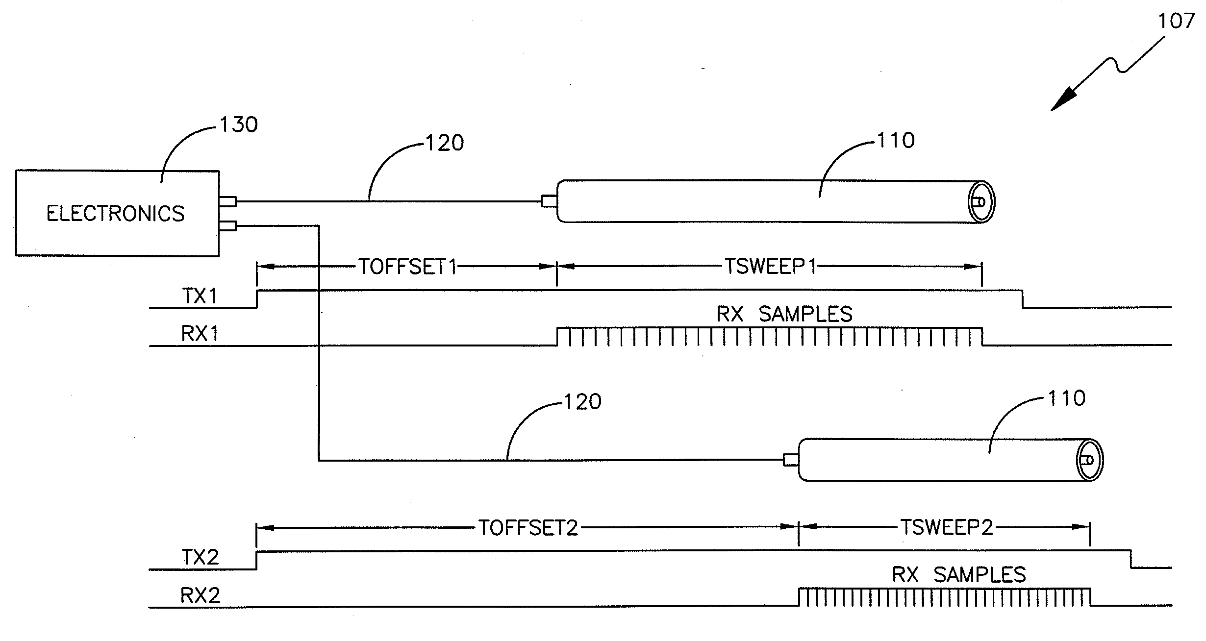
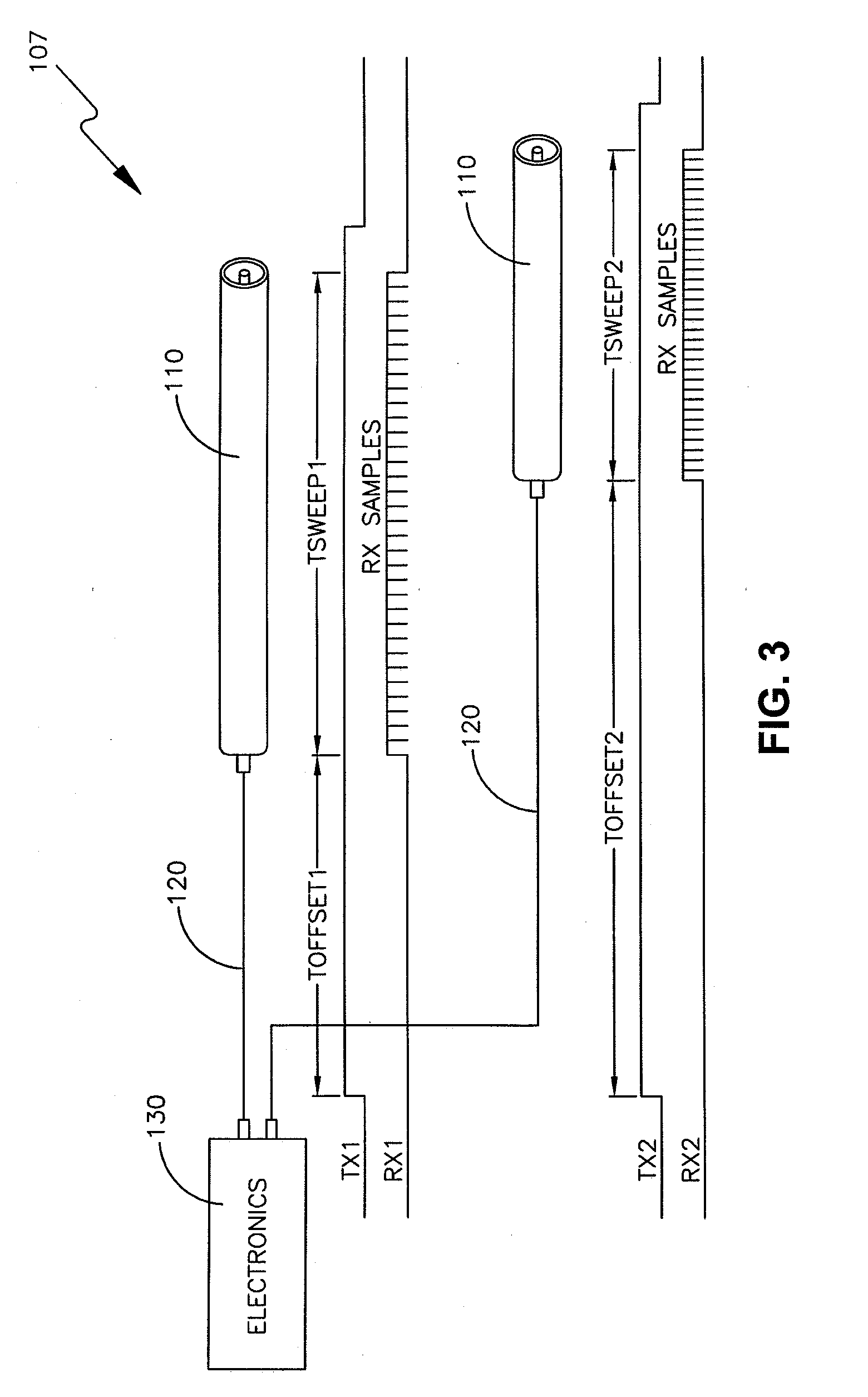
However, even if such optimization were to be carried out as described above so that a reasonable number of samples capable of being collected and processed with satisfactory
response time were collected at times between the approximate time when an interrogation pulse edge reflected from the top of the probe would have just arrived at the
receiver and the approximate time when an interrogation pulse edge reflected from the bottom of the probe would have just arrived at the
receiver, there is still the problem of variability in the parameters affecting those reflected pulse arrival times.
Furthermore, especially when for reason of convenience or safety there are significant lengths of cable between
digital signal processing electronics and probe(s), collection of samples at locations (times) not corresponding to a probe will result in poor
response time and / or poor resolution.
Moreover, even if sweep
delay and
aliasing were to be optimized for a particular cable-probe-tank system so as to permit maximum resolution of the impedance variations occurring along the length of the probe in correspondence to the available
sample processing capacity of the electronics as described above, a technical problem that would remain is the question of what
algorithm will permit most accurate determination of the height profile of the various layers in which the TDR probe is immersed within the tank.
This being the case, the large-amplitude pulse reflected from the probe bottom may
swamp or overwhelm pulses reflected from air-liquid or liquid-liquid interfaces, making detection of those interfaces difficult, when those interfaces are close to the probe bottom (which is typically in the vicinity of the tank bottom).
Thus, a heretofore unaddressed need exists in the industry to address the aforementioned deficiencies and inadequacies.

