Step-down switching regulator, control circuit thereof, and electronic device using the same

a technology of step-down switching and control circuit, applied in the direction of electric variable regulation, process and machine control, instruments, etc., can solve the problems of increased circuit area, waste of power consumption, and difficult operation of the circuit, so as to improve efficiency and increase the effect of the circuit area

Active Publication Date: 2010-06-24
ROHM CO LTD
View PDF8 Cites 40 Cited by
  • Summary
  • Abstract
  • Description
  • Claims
  • Application Information

AI Technical Summary

Benefits of technology

[0011]The present invention has been carried out in view of these problems, and has as a general purpose the provision of a step-down switching regulator which improves efficiency when loading is light, while curtailing an increase in circuit area, and of a control circuit therefor.

Problems solved by technology

Here, with a synchronous rectification type of step-down switching regulator, efficiency becomes problematic when the load current is small.
When the current flowing in the output inductor becomes negative, in a time-period in which the synchronous rectification transistor is ON, since the current flowing in the output inductor flows to ground via the synchronous rectification transistor, power consumption is wasted.
When the voltage across the two ends of this resistance element is detected using a comparator, since it is necessary to use a comparator with a very small offset voltage, there has been a problem in that circuit area increases.

Method used


Image

  • Step-down switching regulator, control circuit thereof, and electronic device using the same
  • Step-down switching regulator, control circuit thereof, and electronic device using the same
  • Step-down switching regulator, control circuit thereof, and electronic device using the same

Examples


first embodiment

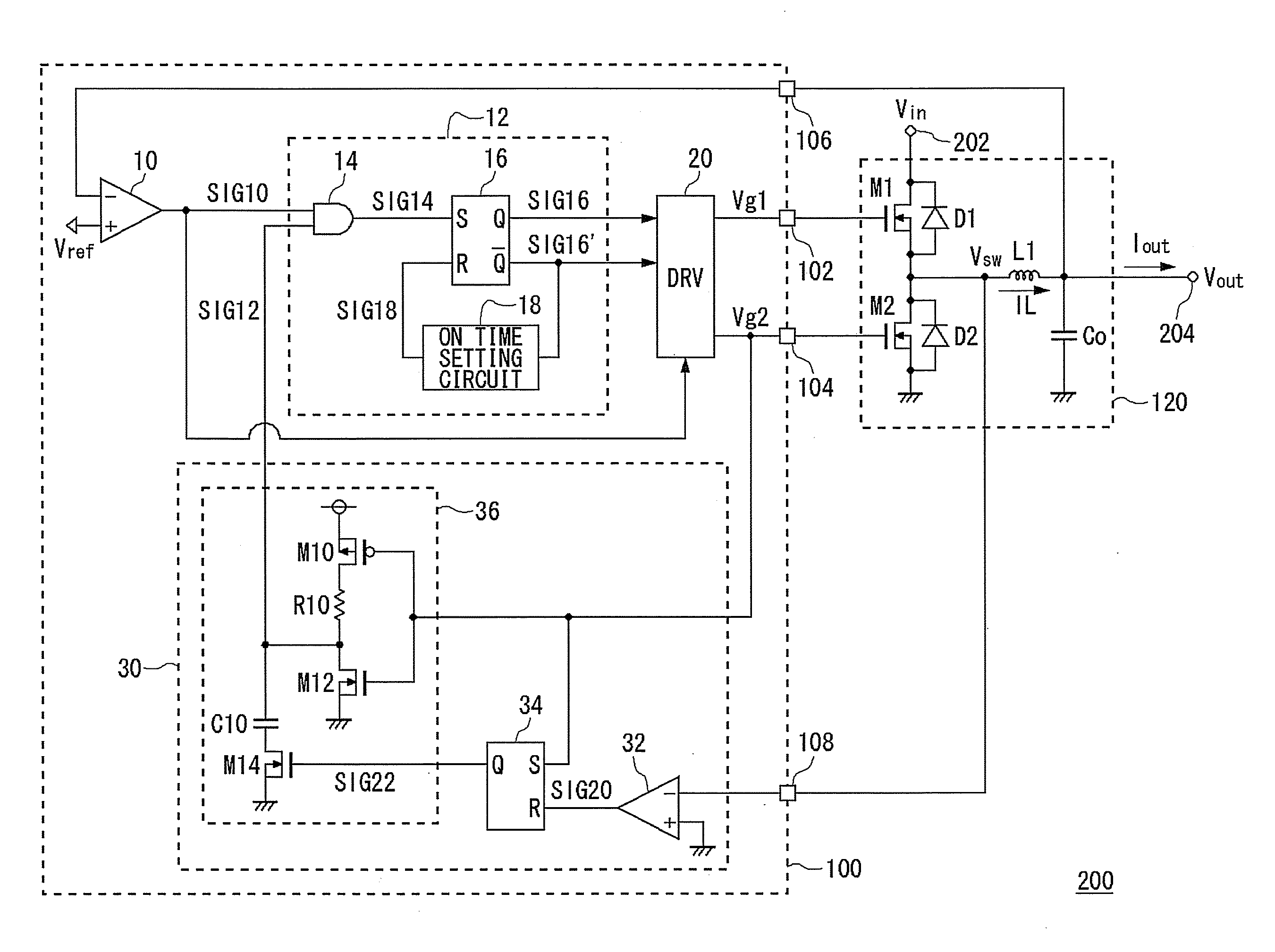
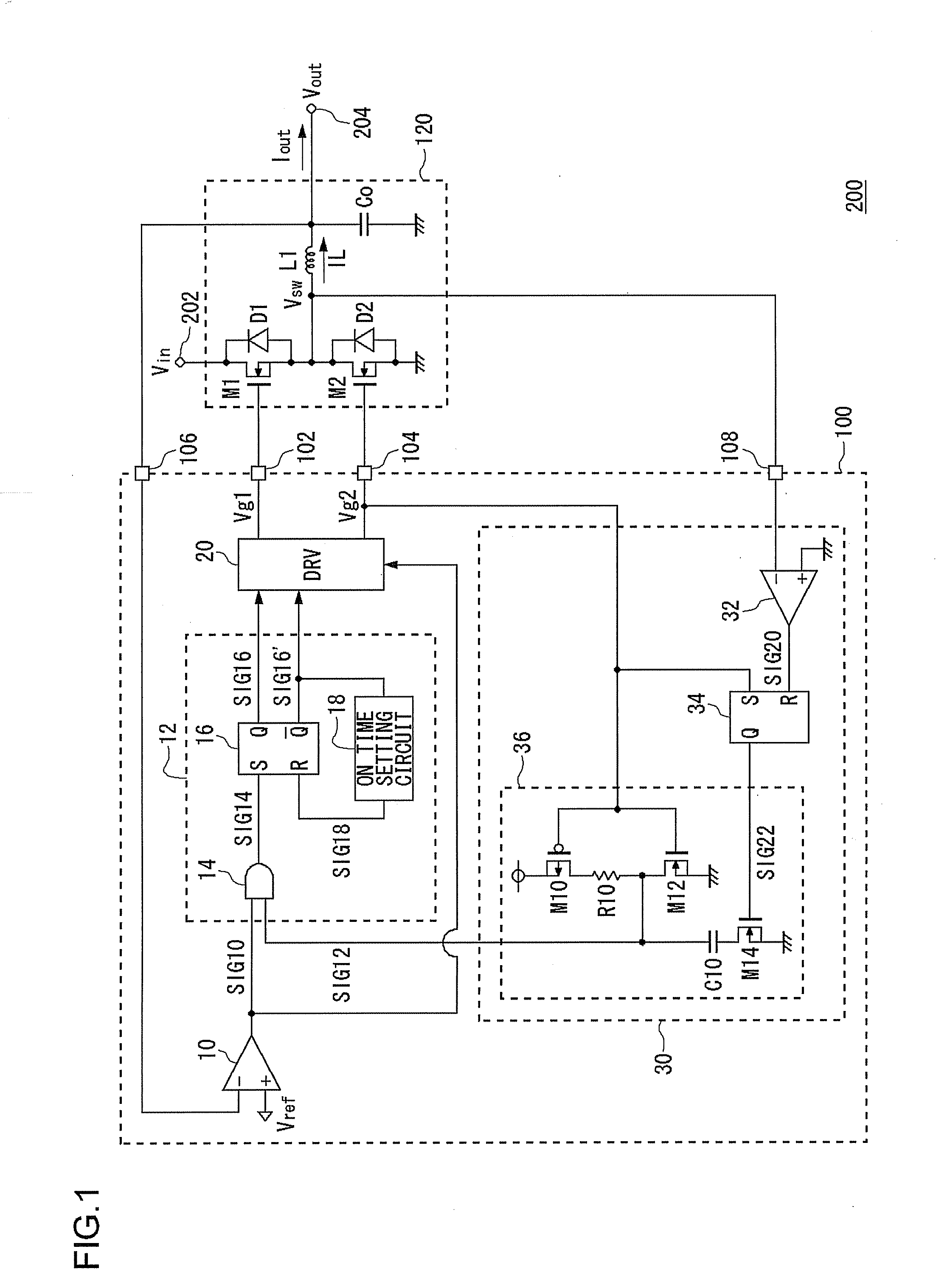
[0043]FIG. 1 is a circuit diagram showing a configuration of a step-down switching regulator 200 according to a first embodiment. FIG. 2 is a block diagram showing a configuration of an electronic device 300 in which the step-down switching regulator 200 of FIG. 1 is installed. The electronic device 300 is, for example, a laptop personal computer, and is provided with a battery 310, a microprocessor 320 and the step-down switching regulator 200.

[0044]The battery 310 is configured from, for example, a plurality of lithium-ion battery cells, and outputs a battery voltage Vbat of about 12 V. The microprocessor 320 performs various arithmetic processing, is a block that performs overall control of the entire electronic device 300, and is an LSI that operates with a power supply voltage of about 1.5 V.

[0045]The step-down switching regulator 200 according to the present embodiment steps down the battery voltage Vbat of about 12 V, to supply the power supply voltage of the microprocessor 3...

second embodiment

[0092]FIG. 8 is a circuit diagram showing a configuration of a step-down switching regulator 200a according to a second embodiment. In the same figure, component elements that are the same or equivalent to FIG. 1 are given the same reference symbols, and explanations are omitted as appropriate. Below, explanations center on differences from the step-down switching regulator 200 of FIG. 1 explained in the first embodiment.

[0093]A control circuit 100a of FIG. 8 differs from the control circuit 100 of FIG. 1 in configuration of the light load mode detector 30 and the driver circuit 20.

[0094]A light load mode detector 30a of FIG. 8, in addition to the light load mode detector 30 of FIG. 1, is further provided with a third dead time generation circuit 40, an inverter 44, and an AND gate 46.

[0095]The third dead time generation circuit 40 outputs a signal SIG30, in which a negative edge of the second control signal Vg2 is delayed. The inverter 44 inverts an output signal SIG30 of the third...


PUM


Abstract

An output monitoring comparator outputs an ON signal when an output voltage becomes lower than a reference voltage. A pulse modulator generates a pulse signal at a predetermined level, an ON time-period from when the ON signal is outputted. A driver circuit alternately turns ON, after a dead time, a switching transistor and a synchronous rectification transistor, based on the pulse signal. A light load mode detector compares a switching voltage at a connection point of the switching transistor and the synchronous rectification transistor, and ground potential, and at timing at which the ON signal is outputted from the output monitoring comparator, when the switching voltage is higher than the ground potential, nullifies the ON signal.

Description

1. FIELD OF THE INVENTION[0001]The present invention relates to a step-down switching regulator, and in particular to control technology for a synchronous rectification type of switching regulator.2. DESCRIPTION OF THE RELATED ART[0002]In recent years, microprocessors for performing digital signal processing are being installed in various electronic devices, such as mobile telephones, PDAs (Personal Digital Assistants), laptop computers, and the like. Power supply voltage necessary for driving these microprocessors decreases with miniaturization of semiconductor manufacturing processes, and there are devices that operate at low voltages of 1.5 V or below.[0003]At the same time, lithium-ion batteries or the like are installed as power sources in these electronic devices. Since the voltage outputted from lithium-ion batteries is approximately 3 V to 4 V, and since power consumption is wasted in supplying the voltage as it is to the microprocessor, in general, battery voltage is steppe...

Claims


Application Information

Patent Timeline
Patent Type & Authority Applications(United States)
IPC IPC(8): G05F1/10
CPCH02M3/1588Y02B70/16Y02B70/1466H02M2001/0032H02M1/0032Y02B70/10H02M7/21
Inventor SAKAI, MASARUUMEMOTO, KIYOTAKA
Owner ROHM CO LTD
Why Eureka
Try Eureka