
Ultrasonic injection molding on a web

a technology of injection molding and ultrasonic injection, applied in the field of ultrasonic assisted molding methods, can solve the problems of difficult molds and subsequent processing and handling of molded articles having delicate structures thereon, and achieve the effects of shortening mold cycle times, good fidelity, and good reproduction of very small mold features

Active Publication Date: 2010-06-24
3M INNOVATIVE PROPERTIES CO
View PDF23 Cites 29 Cited by
  • Summary
  • Abstract
  • Description
  • Claims
  • Application Information

AI Technical Summary

Benefits of technology

[0007]Electromagnetic induction (EMI) heating can be used to apply rapid, localized heating of a microstructured tool within an injection mold cavity. EMI can be used to mold parts with sub-5 micrometer features that excellently replicate a mold pattern in a relatively short mold cycle time (e.g., less than 10 seconds) and with significant reduction in in-mold stresses and birefringence in the molded article produced, as compared with articles made without EMI.
[0022]The filling of the very small features of a mold is aided by dynamic mold temperature cycling which controls the use of heat transfer means to adjust mold temperature. In dynamic mold temperature cycling, the mold is first heated to a temperature above the softening temperature of the polymer to be injected (e.g., above 149° C. for polycarbonate). High mold temperature helps to keep polymer melt viscosity low to facilitate filling the mold features and minimize viscoelastic skinning. After formation of the molded part, the mold is cooled below the softening point to help solidify the molten polymer. Methods of mold temperature thermal cycling are described in PCT Publication WO 2005 / 082596 and U.S. Pat. No. 5,376,317.
[0025]In the inventive method, filling mold features is also aided by use of ultrasonics and / or EMI heating of mold parts as part of the molding cycle. After the polymer melt has filled the mold cavity, the mold is cooled to a temperature below the polymer glass transition temperature to allow for ejection of the molded article from the cavity. The combination of process parameters in the inventive process enable shorter mold cycle times than are practical by practicing the prior art. The inventive process and apparatus enable injection molding microstructured articles (having features with dimensions of less than 5 μm) with good fidelity (i.e., good reproduction of the very small mold features) and mold cycle times of 20 seconds or less.

Problems solved by technology

Molded articles having delicate structures thereon can be challenging to mold and subsequently process and handle.

Method used


Image

  • Ultrasonic injection molding on a web
  • Ultrasonic injection molding on a web
  • Ultrasonic injection molding on a web

Examples


example

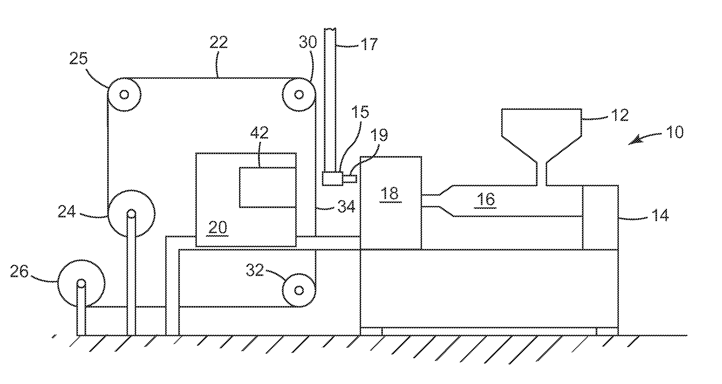
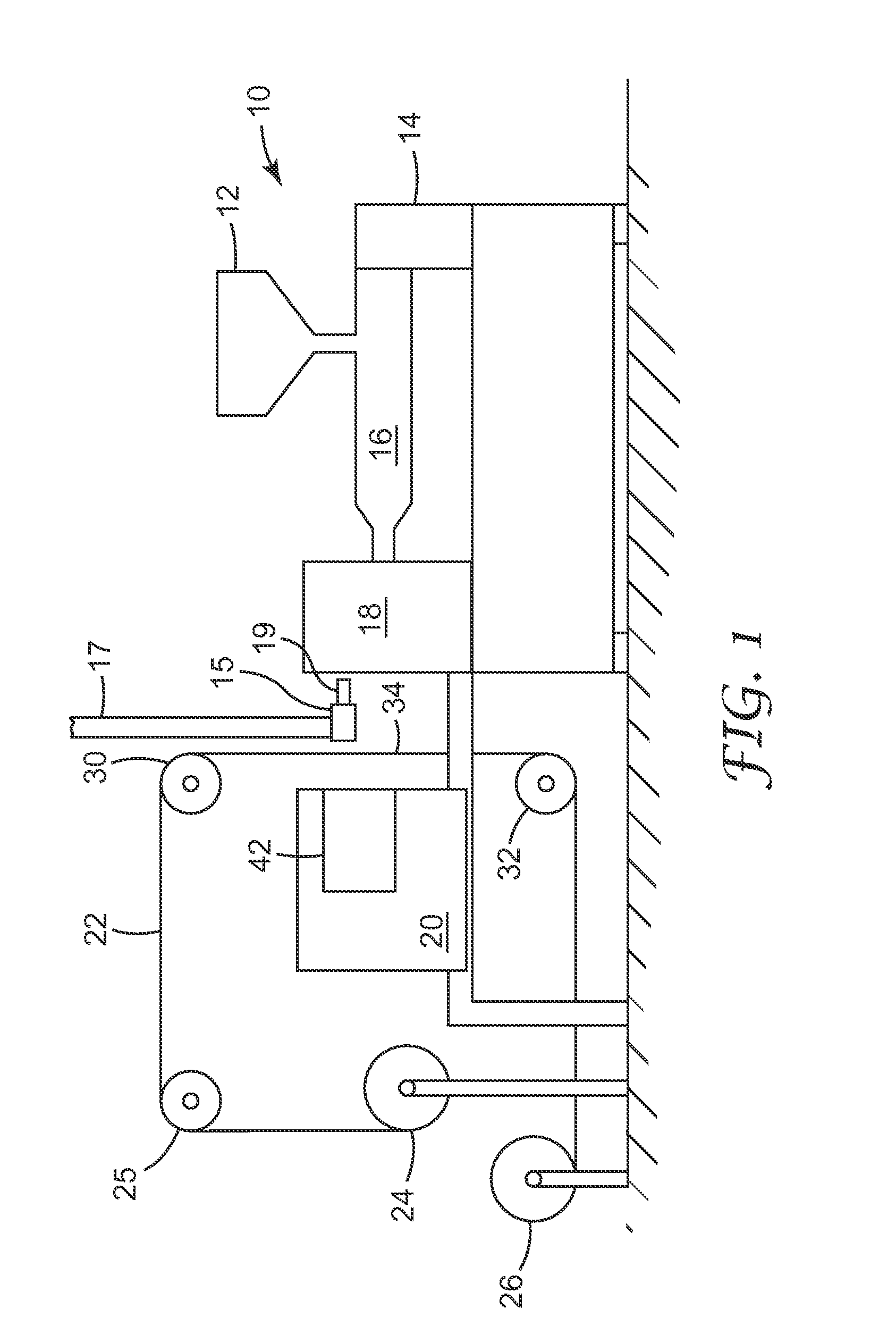
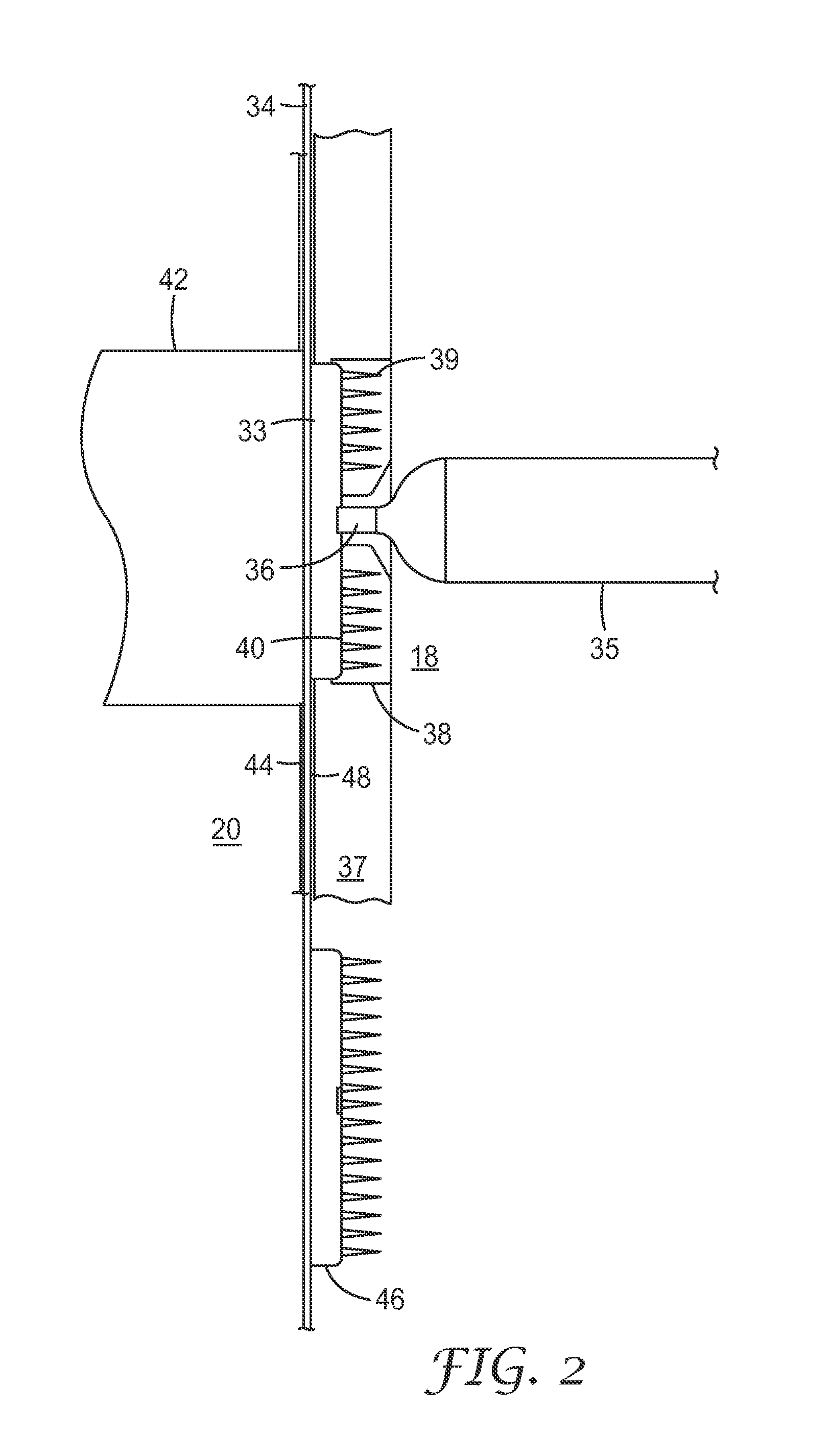
[0082]An 8 cavity center gated hot runner mold was used to deliver molten polycarbonate resin at 293° C. to a circular mold cavity containing an insert having 1288 microcavities for microneedles 250 μm tall with an aspect ratio of about 3, a pitch (W) of 275 μm and tips having a 5 μm radius, to be molded on a circular land or disc about 1.4 cm in diameter. Experiments were conducted with and without EMI heating using a pneumatically driven linear actuator to place an external 1500 W EMI heater between the first and movable members of the injection mold. Electromagnetic induction was applied for periods ranging from 3 to 8 seconds using a gap of 1 mm between the end of the induction coil housing and the plane of the mold plate face. A hot manifold system was used to feed polymer melt to the mold cavities via the hot runners. A polycarbonate carrier web was indexed between the first and movable mold members.

[0083]Vertical movement of the linear actuator for the electromagnetic inducti...


PUM

PropertyMeasurementUnit
Fractionaaaaaaaaaa
Heightaaaaaaaaaa
Surfaceaaaaaaaaaa

Abstract

Injection molding, parts onto a carrier web (34) located between mold halves (18,20). Flow of polymer melt into the mold is assisted by application of ultrasonic energy to the mold cavity. After the molding operation, mold halves are separated, and the carrier web is advanced, or indexed, to a next position for another molding sequence. Molding apparatus comprises a moving mold face (20), that can move toward and away from a first mold member (18) (which can be stationary) in which the mold cavity is located, a means (24,25,26,30,32) for moving and / or indexing carrier web between the first mold member and the moving mold face, means (16) to inject polymer melt into the mold cavity, and an ultrasonic system (42) providing ultrasonic energy to the mold cavity. The carrier web can transport molded parts to subsequent process steps, such as coating, drying, inspection, curing, assembly or packaging.

Description

CROSS-REFERENCE TO RELATED APPLICATIONS[0001]This application claims priority to U.S. Provisional Patent Application Ser. Nos. 60 / 945,217 and 60 / 945,224 both filed Jun. 20, 2007, the entire contents of which are incorporated herein by referenceTECHNICAL FIELD[0002]The present disclosure relates to ultrasonic assisted molding methods and related devices.BACKGROUND[0003]Molded articles are well known and commonly used. Molded articles having delicate structures thereon can be challenging to mold and subsequently process and handle. Injection molding small delicate structures is typically accomplished by injecting molten material into a mold cavity and applying additional heat to the molten material while in the mold and allowing additional time for the molten material to flow into the small cavities in the mold.[0004]A method of molding microneedles is disclosed in International Publication WO 2005 / 082596, and a method which may include the use of ultrasonic energy is disclosed in Int...

Claims


Application Information

Patent Timeline
IPC IPC(8): B29C33/42B29C45/72B81C99/00
CPCB29C45/14016Y10T428/24355B29C45/34B29C45/568B29C45/73B29C2045/0094B29C2045/14942B29C2045/2683B29C2791/008B29L2011/0016B29L2031/753B29L2031/756B29C45/1671B29C45/14B29C2035/0811A61M37/0015A61M2037/0053B29C45/1634B32B3/10G02B3/00B29D11/00009B01F13/0827Y10T428/24479Y10T428/24917Y10T428/24802Y10T428/2481B29C45/27Y10T428/24612B29K2069/00B29K2669/00B01F33/453B29C45/56
Inventor FERGUSON, DENNIS E.NAYAR, SATINDER K.BENSON, PETER T.RENDON, STANLEYPOCHARDT, DONALD L.DOBBS, JAMES N.CARLSON, DANIEL H.
Owner 3M INNOVATIVE PROPERTIES CO
Learn More