
Deltoid main wing aerodynamic configurations

a technology of aerodynamic configuration and delta wing, which is applied in the direction of canard-type aircraft, wing shapes, transportation and packaging, etc., to achieve the effects of high maneuverability at combat speed, low radar and visual reflection, and long-rang

Inactive Publication Date: 2010-07-01
DIZDAREVIC FARUK +1
View PDF32 Cites 70 Cited by
  • Summary
  • Abstract
  • Description
  • Claims
  • Application Information

AI Technical Summary

Benefits of technology

[0018]My “Deltoid Main Wing” idea is providing for the following advantages:

Problems solved by technology

The increased surface area of wings that substitutes fuselage provides for either a higher lift capacity or ability to fly at lower attack angles, thereby resulting with lower profile, induced, and friction drag.
The increased thickness of the wings in the payload area is resulting with increased relative thickness of airfoils and consequently increased profile drag.
However, the absence of the tailplane of “Tailess Flying Wing” concept is having significant negative effects on flight efficiency, as well as the maneuver and flight safety of such aircraft.
A significantly increased relative thickness of airfoils and the absence of the efficient pitch control functions of the tailplane have been the biggest constraints of the flying wing idea that prevented it from being widely implemented for mass air transportation despite great initial promises.
However, this aircraft does not meet longitudinal dynamic stability requirements for civil aviation, while being prohibitively expensive, hence it does not represent a serious theoretical and practical base for development of the flying wing aircraft for civil mass air transportation.
The latest project related to the flying wing concept for civil air transportation is the Boeing's BWB-450 baseline version that is based on the “Tailess Flying Wing” concept, which despite significant improvements relatively to the prior BWB generations did not resolve the key shortcomings and limitations when compared to the classical concept aircraft as follows:It does not provide for a realistic position of gravity center with positive static margin due to unfavorable longitudinal distribution of payload, fuel, and airframe mass relatively to the neutral point, hence consequently being dynamically unstable in longitudinal direction.It does not allow for the utilization of efficient airfoils with aft camber due to the fact that the neutral point and gravity center of the aircraft are significantly shifted in forward direction relatively to the mean aerodynamic chord.
Reflexed airfoils have a significantly lower efficiency at high subsonic and transonic speeds, thus considerably decreasing the initial advantages of the BWB concept.It does not allow for the utilization of trailing edge flaps at low speeds during takeoff and landing, which in turn calls for a flight profile with high attack angles during landing, thus having significant negative repercussions on flight safety and ride quality.It has a significantly lower longitudinal trim efficiency in cruising flight conditions due to a short distance of trim surfaces from the aircraft gravity center and the long mean aerodynamic chord of the airlifting surface.It has a significantly lower level of longitudinal maneuverability especially at low flight speeds due to a short distance of maneuvering surfaces from the aircraft gravity center.In addition, the problem related to high relative thickness of airfoils in the payload area was not satisfactorily resolved despite certain improvements relatively to the previous BWB generations.
The relative thickness of airfoils in the payload area of the BWB concept is in the range between 10% and 15%, which is significantly increasing the compression and wave drag at flight speeds over Mach 0.8, thereby additionally decreasing the aircraft efficiency.
The significant negative aspects in connection with the efficiency and flight safety of the “Tailess Flying Wing” concept, which are related to inability to provide for efficient pitch control without tailplane resulted with the emergence of various hybrid versions of the flying wing concept with the tailplane.
However, the following are the negative effects of designs that were presented in the above patents:The application of thick airfoils due to short chords in the payload area, thereby reducing the aerodynamic efficiency at higher subsonic speeds.Rough aerodynamic transitions in lateral direction between the airlifting surface of fuselage and the airlifting surface of outer wings, thereby drastically increasing the interference drag and resulting with more complex airframe configurations from the manufacturing point.All aerodynamic shapes from the prior art listed above are configured for low subsonic speeds only, which limits their application range.
However, a more detailed and encompassing aerodynamic analyses of this concept showed that the longitudinal position of the tailplane, which depends on the semi-elliptical form of the central section trailing edge was not sufficiently shifted in aft direction to provide for the application of efficient supercritical airfoils in the payload area including the inability to deploy trailing edge flaps during landing and take-off for the same reason.
The further elongation of semi-elliptical trailing edge of the central section with intention to additionally shift the tailplane in the aft direction would inefficiently increase the area of the airlifting surface, thereby increasing the friction drag and significantly decreasing the positive effects gained by shifting the tailplane in aft direction.

Method used


Image

  • Deltoid main wing aerodynamic configurations
  • Deltoid main wing aerodynamic configurations
  • Deltoid main wing aerodynamic configurations

Examples


Embodiment Construction

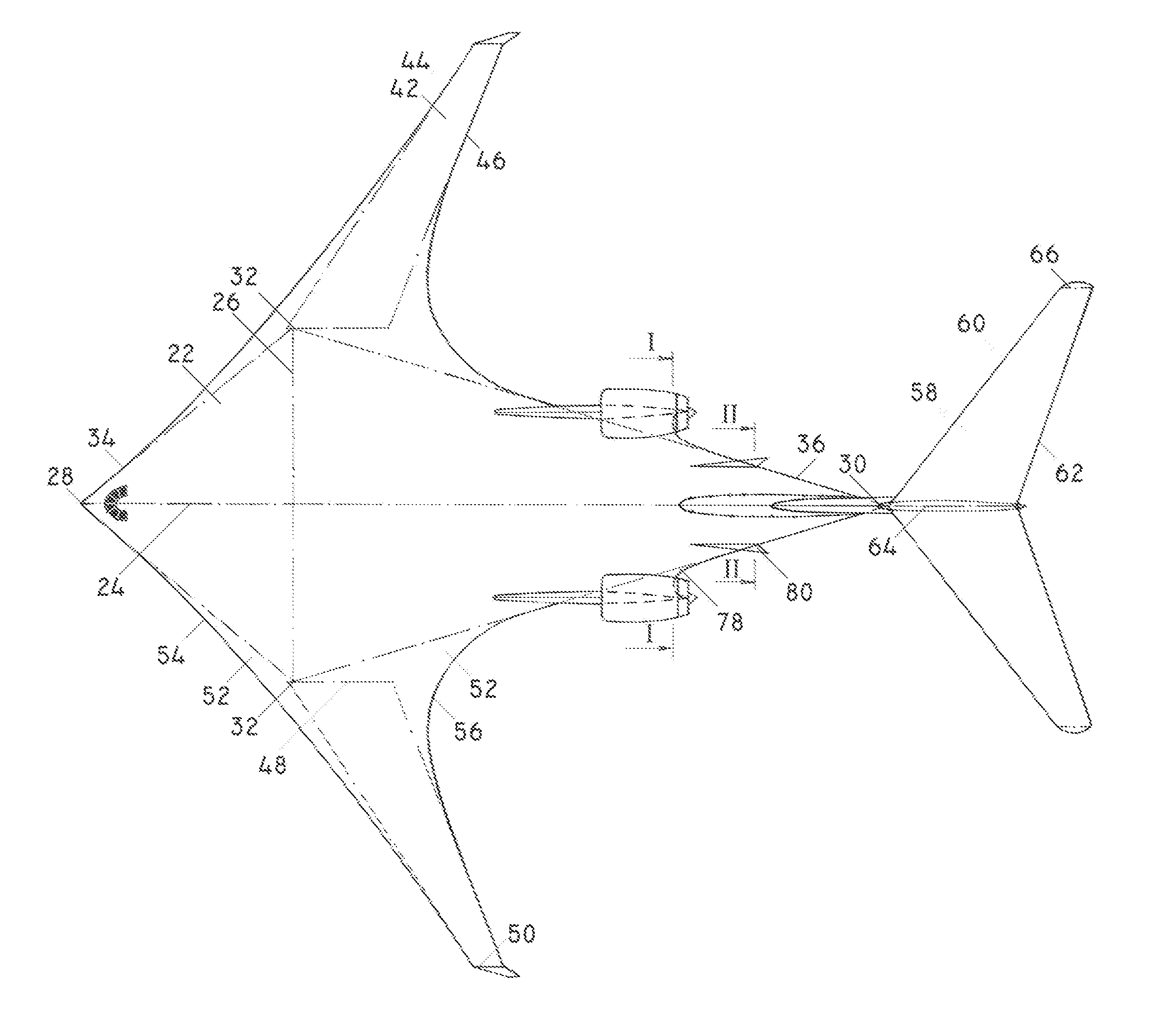
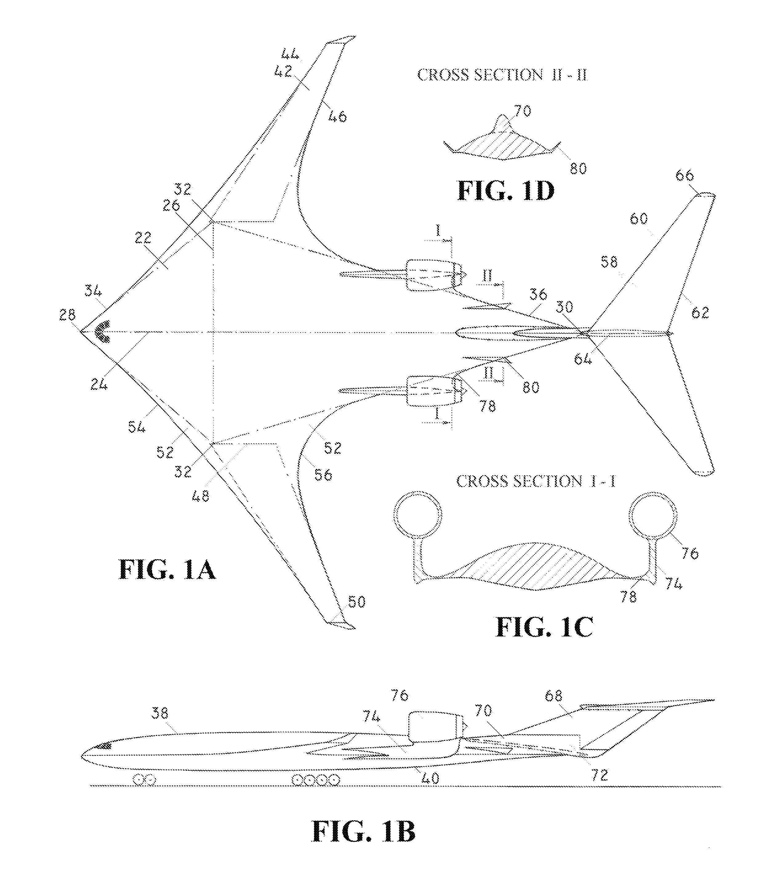
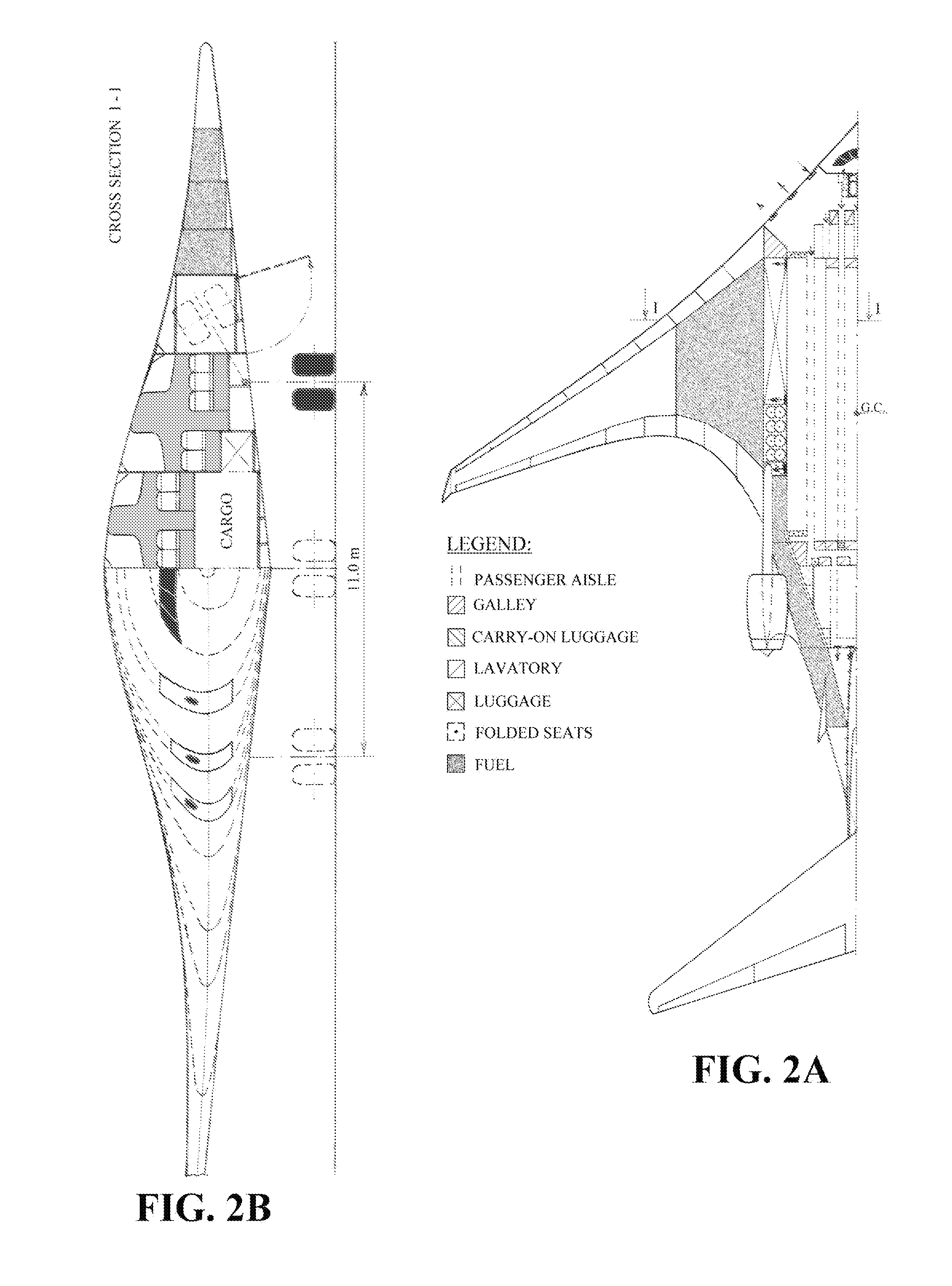
[0044]FIG. 1 shows a TDMW aircraft, which represents an innovative and advanced aerodynamic concept for large high-subsonic and transonic aircraft with economical cruising speed of up to Mach 0.9. The main innovation of this novel and advanced aerodynamic concept refers to a new and innovative shape of the airlifting surface, a new and innovative integration of jet engines with the airlifting surface, as well as a new and innovative integration of tailplane (58) with the airlifting surface, which provides for a high aerodynamic efficiency at high subsonic and transonic speed, as well as a high flight performance in all flight regimes, while meeting all safety requirements for civil air transportation.

[0045]Main wing (22), two outer wings (42), two outer wing transition sections (52), and two jet engine pylon transition sections (74) are smoothly integrated into a single integral airlifting surface of the TDMW aircraft. Main wing (22) is the largest section of the integral airlifting...


PUM


Abstract

Deltoid Main Wing idea provides for several innovative aerodynamic configurations for large subsonic and supersonic civil and military aircraft including “T-tailed Deltoid Main Wing” configuration that allows for design of high-subsonic jumbo jet passenger aircraft with a capacity between 200 and 700 passengers whose outer dimensions fit within 80 m box on class VI airports while having more than twice lower fuel consumption per unit of payload when compared to the present classical-concept aircraft with the same passenger capacity, while further allowing for design of all-size and all-purpose, high-lift-capacity, and long-range unmanned aircraft.

Description

BACKGROUND OF THE INVENTION[0001]The flying wing idea was born in the early historical phase of the aircraft development with the goal to eliminate all external sections that do not participate actively in the lift production, hence minimizing drag, increasing lift capacity, and reducing the fuel consumption. Initially, the flying wing idea anticipated only wings with power plant without fuselage and tails. The elimination of fuselage required a certain increase of the chords and thickness of wings in order to provide for required payload accommodation. The increase of wing chords is increasing the airlifting surface area of wings. The increased surface area of wings that substitutes fuselage provides for either a higher lift capacity or ability to fly at lower attack angles, thereby resulting with lower profile, induced, and friction drag. The increased thickness of the wings in the payload area is resulting with increased relative thickness of airfoils and consequently increased p...

Claims


Application Information

Patent Timeline
IPC IPC(8): B64C1/00
CPCB64C1/0009B64C3/10B64C30/00B64C39/12B64C2039/105Y02T50/12Y02T50/10B64U30/10B64U50/13B64U20/77
Inventor DIZDAREVIC, FARUKDIZDAREVIC, MITHAD
Owner DIZDAREVIC FARUK
Learn More