Method for on board decarbonization of hydrocarbon fuels in a vehicle

a technology for hydrocarbon fuels and vehicles, applied in fuel systems, non-fuel substance addition to fuels, inorganic chemistry, etc., can solve the problems of insufficient reduction of co2 to maintain an acceptable level, inconvenient operation, and insufficient reduction of co2 to achieve the effect of maintaining an acceptable level of co2

Active Publication Date: 2010-07-15
SAUDI ARABIAN OIL CO
View PDF20 Cites 16 Cited by
  • Summary
  • Abstract
  • Description
  • Claims
  • Application Information

AI Technical Summary

Benefits of technology

[0013]The hydrogen or hydrogen-rich gas that has been separated from the carbon can be fed to the ICE, increasing the fuel's overall hydrogen-to-carbon ratio. This will result in a reduction in CO2 emissions, and will also have a positive effect on the vehicle's overall fuel combustion efficiency.
[0014]The hydrogen generated can also be utilized for other on-board applications, such as powering a fuel cell-based auxiliary power unit that will also contribute to enhanced fuel efficiency and which would otherwise require a dedicated on-board fuel reformer.
[0017]Carbon storage and collection systems, including pumps and conduits, are currently available and can be installed at existing fueling stations. Instead of being a liability, the carbon (which constitutes the major portion of hydrocarbon fuels) is separated by this invention in the form of a useful material that can be used as a feedstock for important domestic and international manufacturing industries, or as a fuel or fuel extender for boilers, gasifiers and industrial furnaces. The implementation of this invention will eliminate the need for a costly transition to alternative carbon-free fueling infrastructure, and will create new business opportunities for establishing a parallel carbon-based industry.

Problems solved by technology

These techniques are impractical in the case of mobile vehicular systems such as automobiles, trucks and buses, principally due to the associated high cost and limited availability of on-board space.
However, the extent of these reductions may not be sufficient to maintain an acceptable level of CO2 emissions in view of the rapidly growing automotive transportation sector.
These alternative systems, however, will require substantial alterations to the transportation fueling infrastructure that has been developed on a worldwide basis over the past century.

Method used


Image

  • Method for on board decarbonization of hydrocarbon fuels in a vehicle
  • Method for on board decarbonization of hydrocarbon fuels in a vehicle

Examples


first embodiment

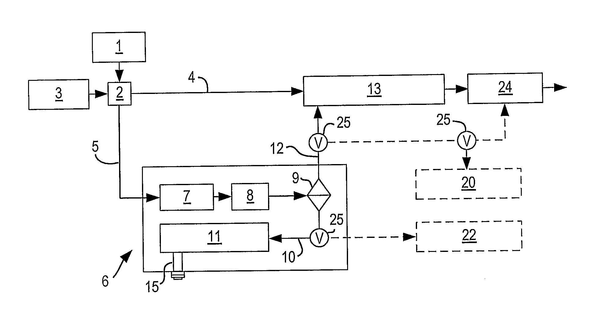
[0023]In the first embodiment, shown in FIG. 1, all or a portion of the fuel is fed to the decomposer 7 where it decomposes or cracks in the absence of air, thereby producing elemental carbon and hydrogen. Depending upon the thermal decomposition efficiency, it is possible that gaseous hydrocarbon compounds will be produced along with the hydrogen. These gaseous hydrocarbon compounds can include methane, ethane, and traces of C3 compounds. Where the fuel contains oxygenates, the thermal decomposition products will include CO and CO2.

[0024]The fuel supplied to the decomposer 7 is vaporized, either before or inside the decomposer 7. The thermal decomposition can be achieved by thermocatalysis, a plasma process, or other industrial decomposition processes known to, or to be developed by the art. The heat necessary for the decomposition will be provided by an external source such as electricity, hot exhaust gases, a dedicated burner, or other means presently known in the art or to be de...

second embodiment

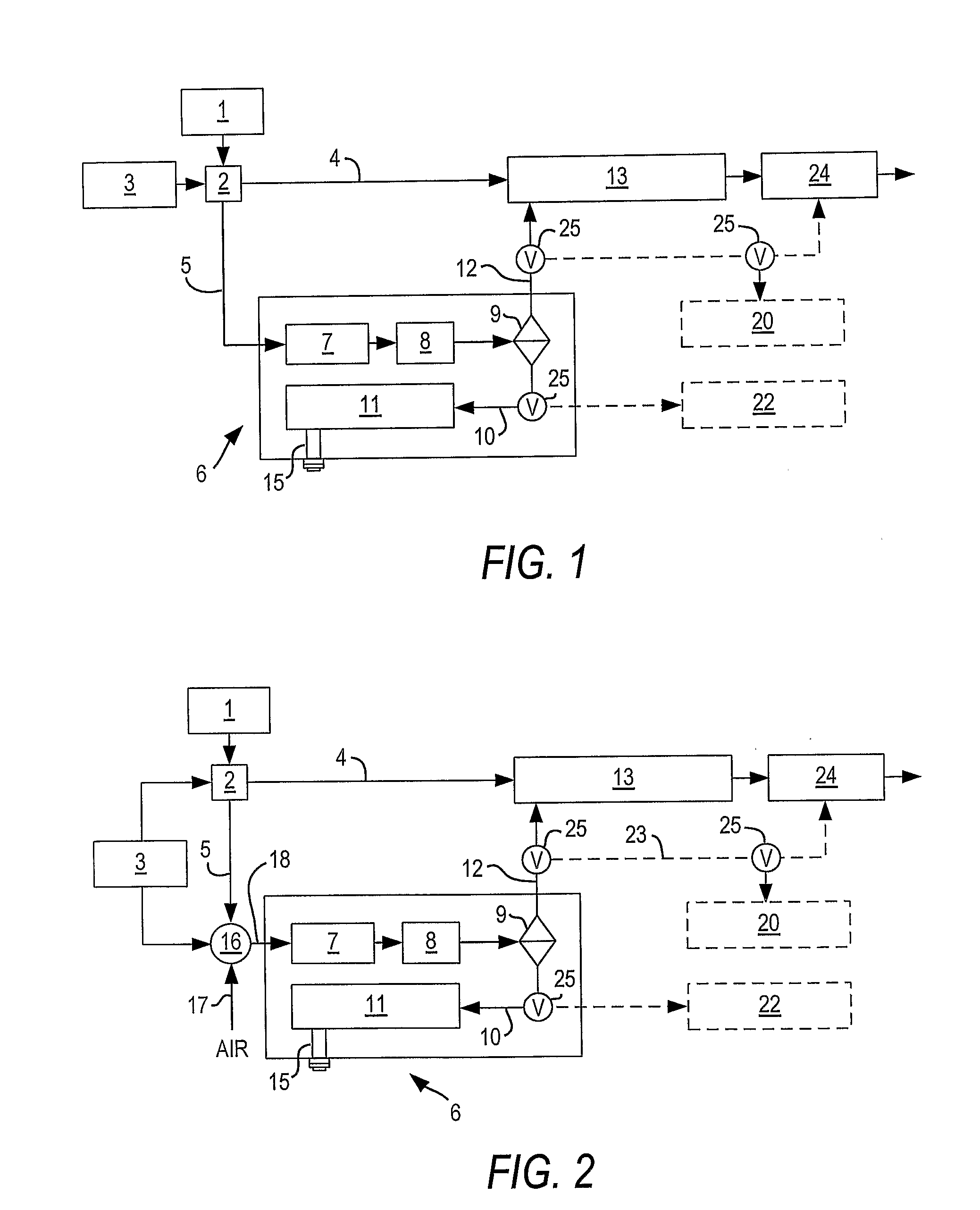
[0027]In the second embodiment, as illustrated schematically in FIG. 2, the fuel coming from fuel system 2 through line 5 is vaporized and mixed with a controlled amount of air (17) in the mixing unit 16. This air-fuel mixture (18) is then fed to decomposer 7 in decarbonization unit 6 where exothermic combustion and endothermic decomposition occur simultaneously using catalytic or non-catalytic media. In this process, the heat released by the partial oxidation reaction will provide all or part of the heat necessary to achieve the thermal decomposition of the hydrocarbon fuel into carbon and a hydrogen-rich gas stream.

[0028]The ratio of the air-fuel mixture introduced into decomposer 7 is adjusted in order to achieve the desired decomposition temperature. External heating, such as the passage of hot exhaust gases through a heat exchanger, can be employed, if necessary, to supplement the internal heating in order to minimize the fuel energy penalty. Thereafter, the temperature is redu...


PUM


Abstract

A method and apparatus for the reduction of carbon dioxide emissions by the on-hoard treatment of a portion or all of the hydrocarbon fuel used to power an internal combustion engine mounted in a conventional transportation vehicle, utilize known decarbonization technology to break the fuel's hydrogen-carbon bond. The compounds are then cooled and separated into (1) elemental carbon powder that is stored on-board for later recovery and industrial use, and (2) hydrogen, or a hydrogen-rich gas stream, that is burned as a fuel in the ICE and / or diverted to other on-board energy related applications.

Description

FIELD OF THE INVENTION[0001]This invention relates to the reduction of carbon dioxide (CO2) emissions from internal combustion engines (ICE) used to power automotive and other vehicles by the on-board treatment of gaseous and / or liquid hydrocarbon fuels.BACKGROUND OF THE INVENTION[0002]There are growing concerns about the apparent relationship of increasing the concentration of greenhouse gases and the global warming phenomenon. As a consequence, a broad consensus has developed as to the need to reduce CO2 emissions associated with various human activities.[0003]Carbon dioxide emissions (CO2) from hydrocarbon-fueled transportation vehicles powered by internal combustion engines (ICE) constitute a significant part of the total man-made greenhouse gas emissions. As a result, adoption of new rules to significantly reduce CO2 from vehicles are currently being considered in many countries around the world. As an example, action was recently taken by the State of California to adopt new r...

Claims


Application Information

Patent Timeline
Patent Type & Authority Applications(United States)
IPC IPC(8): F02B43/08
CPCB01D53/005Y02T10/36C01B3/26C01B3/36C01B2203/025C01B2203/0272C01B2203/0277C01B2203/0405C01B2203/049C01B2203/06C01B2203/066C01B2203/0811C01B2203/0822C01B2203/0833C01B2203/085C01B2203/0861C01B2203/0883C01B2203/1217C01B2203/1241C01B2203/1247C01B2203/1276C01B2203/1288C01B2203/169C01B3/24Y02P20/128
Inventor AL-DAWOOD, ALI M.AL-MUHAISH, FAHAD IBRAHIM
Owner SAUDI ARABIAN OIL CO
Why Eureka
Try Eureka