

Lithium energy storage device
a technology of energy storage and lithium, which is applied in the direction of electrochemical generators, cell components, transportation and packaging, etc., can solve the problems of limiting cycle life, fire and explosion, and the tendency of lithium metal electrodes to develop dendrite surfaces, and achieve the effect of improving the electrical conductivity of active metals
- Summary
- Abstract
- Description
- Claims
- Application Information
AI Technical Summary
Benefits of technology
Problems solved by technology
Method used
Image

Examples
example 1
Preparation and Testing of Pyr13FSI with LiTFSI
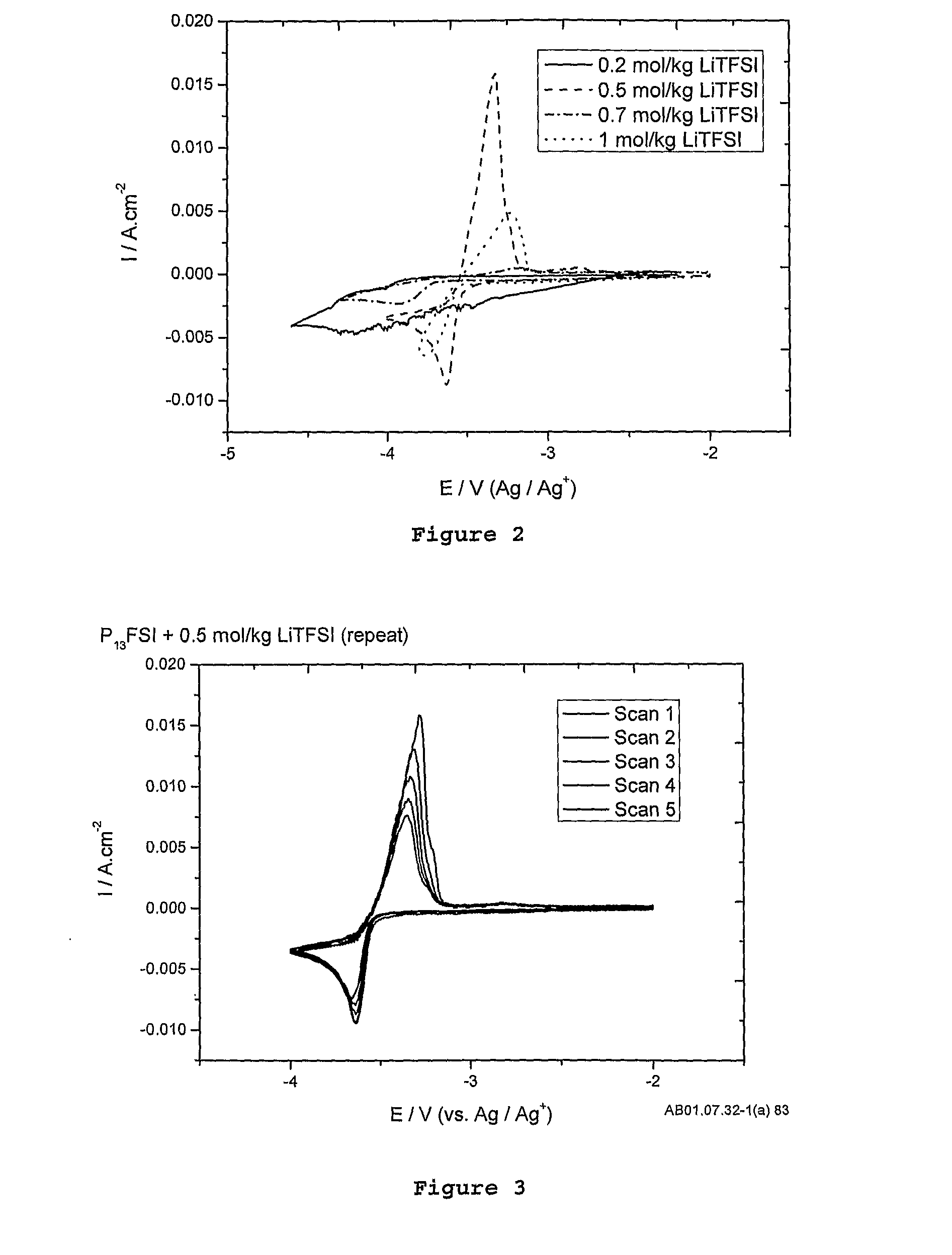
[0128]Lithium bis(trifluoromethansulfonyl)imide (LiTFSI) is dissolved into the Pyr13FSI at a concentration of between 0.2 mol / kg and 1.5 mol / kg, but optimally at 0.5 mol / kg. Stirring may be required to dissolve the salt.
[0129]FIG. 2 shows a comparison of different electrolyte concentrations. From this figure it is observed that at 0.5 mol / kg LiTFSI, the plating and stripping currents on the platinum (Pt) working electrode are maximised due to high conductivity of the electrolyte and high lithium self-diffusion co-efficients. At low salt concentrations (0.2 mol / kg), there is not enough lithium TFSI salt in solution to provide a sufficient mixture of both FSI and TFSI anions to provide an electrochemical window wide enough to (a) establish a stable solid electrolyte interface and (b) enough lithium-ions to plate. At 0.7 mol / kg there was a significant decrease in peak heights for plating and stripping of lithium as the viscosity of the ele...
example 2
Preparation and Testing of Pyr13FSI and LIBF4
[0135]Lithium tetrafluoroborate (LiBF4) was dissolved into the Pyr13FSI at a concentration of between 0.2 mol / kg and 1.5 mol / kg, but optimally at 0.5 mol / kg as determined from electrochemistry, differential scanning calorimetry (DSC) viscosity and Nuclear Magnetic Resonance (NMR) measurements. Stirring may be required to dissolve the salt.
[0136]Using the 0.5 mol / kg LiBF4 salt concentration, a voltammagram between −2 and −4V have been conducted as shown in FIG. 6. The figure shows the plating and stripping of lithium on a platinum electrode.
[0137]To determine the usefulness of the Pyr13FSI+0.5 mol / kg LiBF4 under galvanostatic conditions like those experienced in a real device, symmetrical lithium cells were prepared to understand issues such as polarisation of the electrodes, polarisation of the electrolyte, and the resistances which form within the cell as a function of such cycling. These effects translate into the potentials observed i...
example 3
Preparation and Testing of Pyr13FSI with LiPF6
[0141]Lithium hexafluorophosphate (LiPF6) was dissolved into the Pyr13FSI at a concentration of between 0.2 mol / kg and 1.5 mol / kg, but optimally at 0.5 mol / kg as determined from electrochemistry measurements. Stirring may be required to dissolve the salt.
[0142]Using the 0.5 mol / kg LiPF6 salt concentration, a voltammagram between −2 and −4.25V have been conducted as shown in FIG. 10. The figure shows every second scan of the plating and stripping of lithium on a platinum electrode, the current normalised to the electrode area.
[0143]To determine the usefulness of the Pyr13FSI+0.5 mol / kg LiPF6 under galvanostatic conditions like those experienced in a real device, symmetrical lithium cells were prepared to understand issues such as polarisation of the electrodes, polarisation of the electrolyte, and the resistances which form within the cell as a function of such cycling. These effects translate into the potentials observed in FIG. 11.
[014...
PUM
| Property | Measurement | Unit |
|---|---|---|
| temperature | aaaaa | aaaaa |
| boiling point | aaaaa | aaaaa |
| current densities | aaaaa | aaaaa |
Abstract
Description
Claims
Application Information