Device for the detection of an electromagnetic radiation and electromagnetic radiation detector comprising such devices

a technology of electromagnetic radiation and detector, which is applied in the field of electromagnetic radiation detection devices and electromagnetic radiation detectors, can solve the problems of bolometric detectors, small relative variation of electrical resistance, and detrimental to the quality of infrared radiation detection, and achieve the effect of increasing the complexity of the detector manufacturing process

Active Publication Date: 2010-07-22
ULIS SAS
View PDF5 Cites 25 Cited by
  • Summary
  • Abstract
  • Description
  • Claims
  • Application Information

AI Technical Summary

Benefits of technology

[0051]The purpose of the present invention is to resolve the abovementioned problem by putting forward, in a bolometric detector, a common mode rejection structure which accurately evaluates and compens...

Problems solved by technology

The main difficulty in employing bolometric detectors lies in the very slight relative variation of their electrical resistance, representing local variations in temperature of an observed scene, relative to the mean value of these resistances.
Since ordinary bolometers show very significant sensitivity to such variations, the result of this is that the output signal is disturbed by this parasitic background signal, which is detrimental to the quality of the detection of the infrared radiation.
In fact, the bolometer heats up by joule effect (this is generally known as “self-heating”) further adding thereto a current component causing interference on the wanted signal related to the scene.
On the other hand, providing a reference bolometer 26 for each line in the array of imaging bolometers generates an on-line spatial noise given the technological dispersions of the reference bolometers.
As a result, the self-heating of the reference bolometer 26 differs substantially from the self-heating of the ...

Method used


Image

  • Device for the detection of an electromagnetic radiation and electromagnetic radiation detector comprising such devices
  • Device for the detection of an electromagnetic radiation and electromagnetic radiation detector comprising such devices
  • Device for the detection of an electromagnetic radiation and electromagnetic radiation detector comprising such devices

Examples


Embodiment Construction

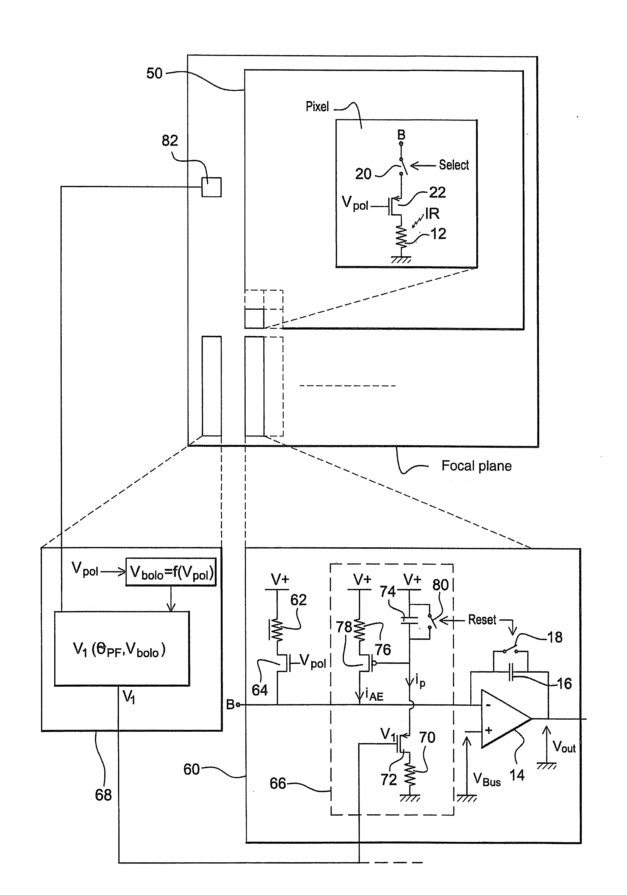
[0093]An inventive bolometric detector is shown in FIG. 5. As has already been previously described in relation to FIGS. 2 to 4, the detector comprises an array of bolometric pixels 50, each of the pixels comprising an imaging bolometer 12 that has a bolometric membrane sensitive to infrared radiation and suspended above a substrate by means of support and thermal insulation arms. The bolometric membrane is of the semi-conductor type, and comprises amorphous silicon or vanadium oxides for example.

[0094]Each pixel in the array 50 also comprises an MOS transistor 22 and a read switch 20. Each column in the array 50 is associated with a read circuitry 60 produced in the substrate. The circuitry 60 comprises an integrator, constituted by an operational amplifier 14, a capacitor 16 and a reset switch 18.

[0095]The circuitry 60 also comprises a compensation bolometer 62 thermalized in the substrate. For example the compensation bolometer 62 has no support arms and / or is partially or totall...


PUM


Abstract

The invention relates to a device for the detection of an electromagnetic radiation including: a substrate; a resistive imaging bolometer; a circuit for polarizing the bolometer at a predetermined voltage; a rejection circuit generating a common mode current, comprising a compensation bolometer thermalized in the substrate and a polarization circuit thereof; and a measuring circuit for measuring the difference between the current flowing in the imaging bolometer when it is polarized and the common mode current generated by the rejection circuit. According to the invention, the rejection circuit further comprises a current generator capable of producing a current that simulates the current induced by the self-heating of the imaging bolometer under the effect of its polarization, the sum of the current passing through the compensation bolometer and the current generated by the current generator forming the common mode current.

Description

FIELD OF THE INVENTION[0001]The invention relates to the field of infrared imaging and pyrometry. To be more specific, the invention relates to common mode rejection when reading bolometers.PRIOR ART[0002]In the field of infrared detectors, there is a known technique of using devices arranged in the form of an array, and capable of operating at ambient temperature, in other words not needing to be cooled to very low temperatures, contrary to the imaging devices known as “quantum detectors”, which, for their part, require an operation at very low temperature, and typically that of liquid nitrogen.[0003]These uncooled detectors traditionally use the variation in a physical quantity of an appropriate material, as a function of the temperature, in the vicinity of 300K. In the case of bolometric detectors, this physical quantity is the electrical resistivity.[0004]An uncooled detector of this kind generally associates:[0005]means for absorbing the infrared radiation and converting it int...

Claims


Application Information

Patent Timeline
IPC IPC(8): G01J5/02
CPCG01J5/22
Inventor LEGRAS, OLIVIER
Owner ULIS SAS
Why Eureka
Try Eureka