This helps you quickly interpret patents by identifying the three key elements:
Problems solved by technology
Method used
Benefits of technology
Benefits of technology
[0057]In theory, utilisation of embodiments of the invention so facilitates increasing the radiation power at the target without limitations, but provide also means to adjust several aspects of the radiation at the working target to match to the appropriate aspect of the invention. Thus this can be made by using one or several diode-pumped radiation sources as a radiation source for the radiation to be guided by an optical path, comprising a turbine scanner, to the working target, essentially without fibre-caused losses in an external optical path.
Problems solved by technology
However, the fibres of the conventional fibre-lasers do not facilitate high-powered, into pulsed shape compressed laser radiation transference into the working target with sufficient net-power.
At required power level in the working target, the conventional fibres do not tolerate the losses in the radiation transference by the absorption of the radiation into the fibre.
One reason, to use fibre-techniques in the laser radiation transference from the source to the target, has been that even a transference of a one single beam through free air is a considerable risk to the employers in industrial working environment and in industrial scale, technically very demanding if were not completely impossible.
The recent fibres of the fibre lasers, as well as the consequent low radiation power limit the materials to be used in the vaporization / ablation as the vaporization / ablation targets.
Most significant obstacle to the forwarding progress of fibre-laser technology seems to be the fibre strength of the fibre to tolerate the high power laser pulses without break-up of the fibre or without diminished quality of the laser beam.
Because the energy content of a pulse, the power of the pulse increases in the decrease of the pulse duration, the problem significance increases with the decreasing laser-pulse duration.
The problems occur significant even with the nano-second-pulse lasers, although they are not applied as such in cold ablation methods.
Manufacturing of such a fibre that would tolerate even 200 kW and pass the 15 ps pulse through with non-distorted optimal pulse shape has been not possible before the priority date of the current application, according to the writer's knowledge.
The problems of the recent fibre-lasers are limited not only to the fibre itself, but concern also to the joining together of separate diode-pumped lasers by the optical connectors, so aiming to gain the desired total power.
Even in the use of the conventional power levels, the manufacturing of the appropriate optical connectors is extremely expensive, the performance is uncertain in some extent and they are consumed up during the use, so they should be replaced with in a time interval.
Method used
Image
Click on the blue label to locate the original text in one second.
Reading with bidirectional positioning of images and text.
Examples
example 1
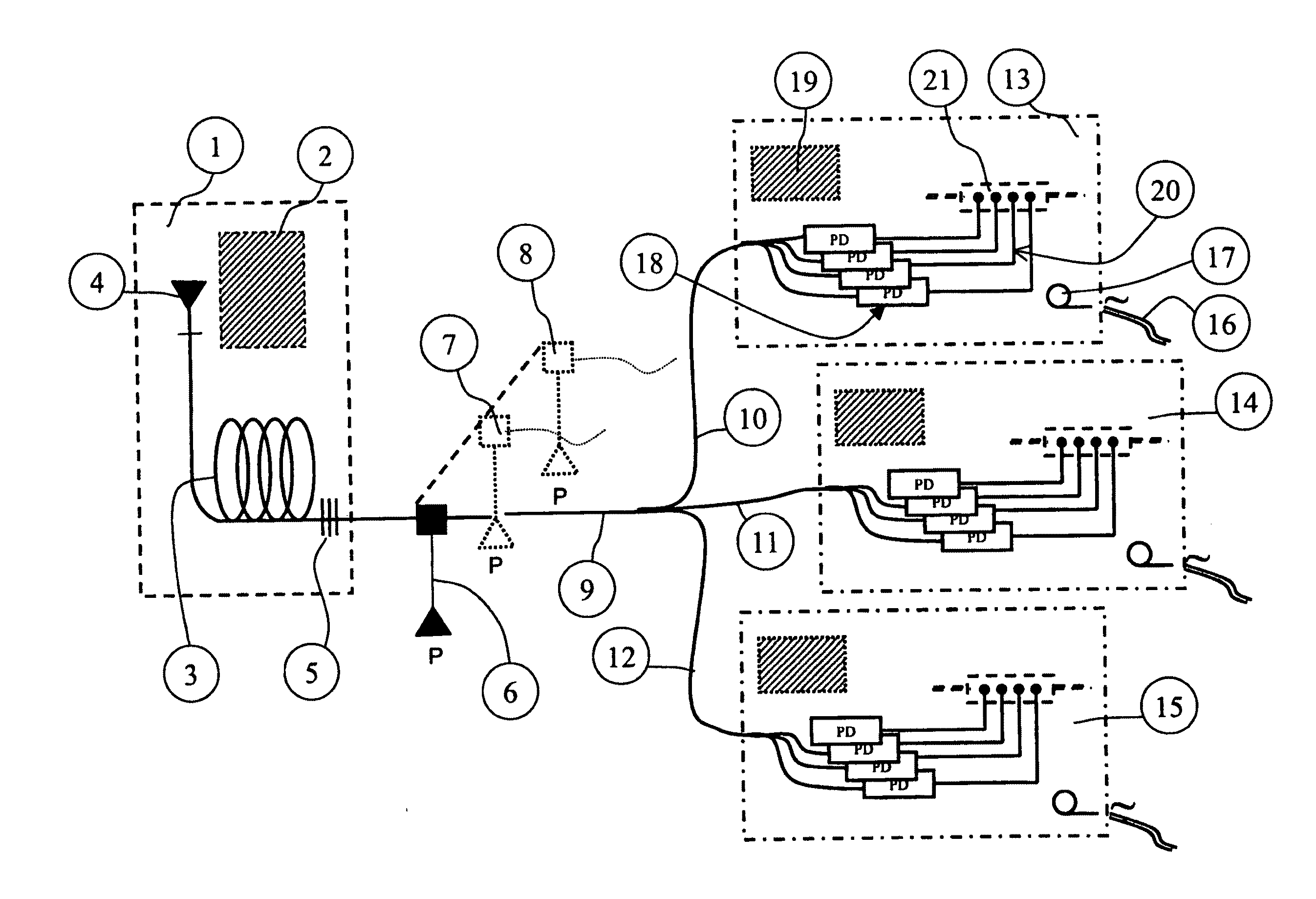
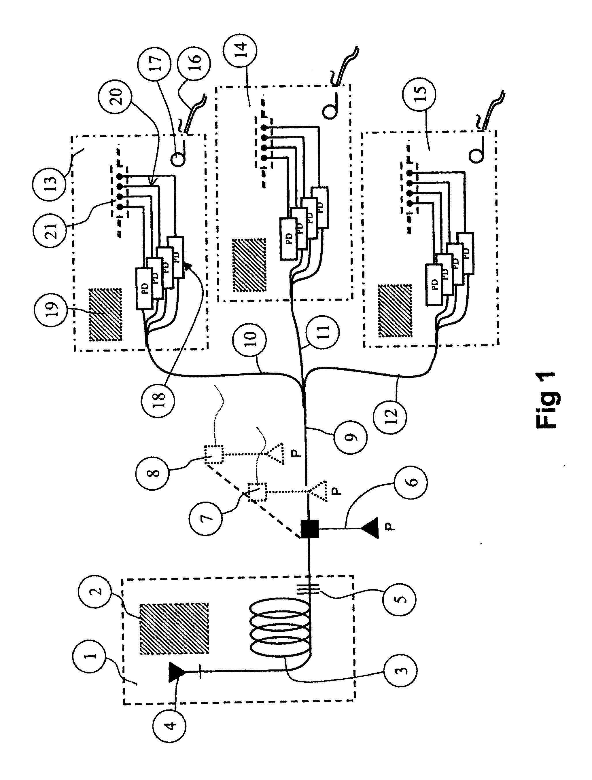
[0238]FIG. 1 illustrates a fibre oscillator (3) and a preamplifier (2), but also formation of an incident laser-light with a diode (4) and sesam-grid (5). The new laser system is a phased-diversified-amplified-direct-mode laser system (-laser system). This is the pre-amplifier unit (1) of the PDADM-laser system, which unit defines the pulse length, pitch, power, and other features of the radiation).
[0239]It is actually a digitally controllable control centre arranged to control the whole radiation source arrangement. The radiation source arrangement is completely fibre-based laser system.
[0240]The second phase laser-pulse gain / amplification (6) resides in the same central unit (1), so that even several parallel amplification units (7) and (8) can be in duty, as depending on the number of desired working spots and / or targets the laser pulses are addressed to as amplified.
[0241]A low powered laser pulse (as a light pulse) (9) is further directed via a divider, say, to three directions...
example 2
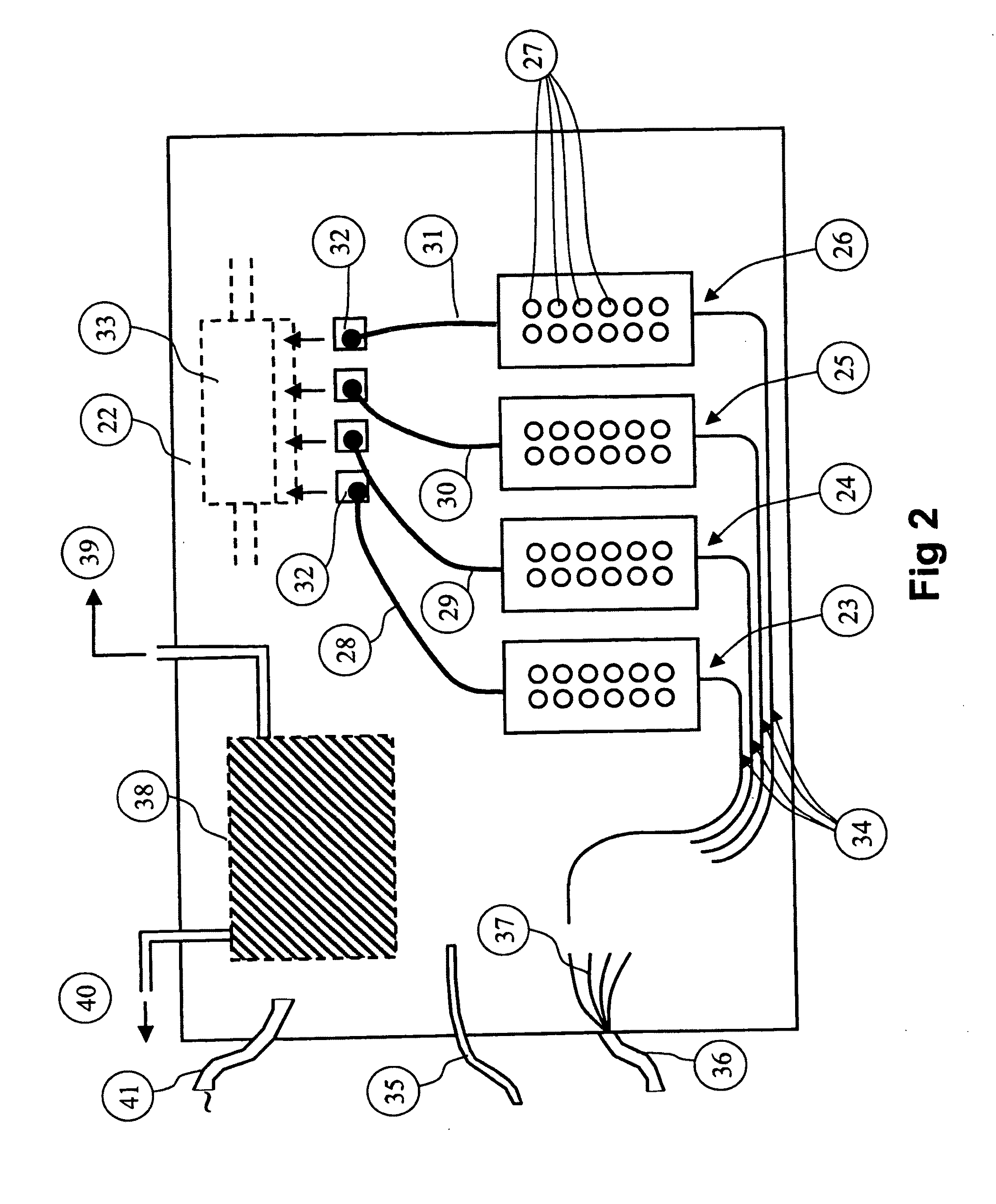
[0249]FIG. 2 illustrates a part of a radiation source arrangement as embodied as a laser related embodiment. In the embodiment, the power-amplifiers, as diode-pumps, are located into a vaporization / ablation system as a part of it, so that high-power laser pulse transference fibres as well as optical connectors for the same are not needed, at least the need appears to be remarkably diminished if not completely ceased. In this example the diode-pumps are in the vacuum vaporization / ablation device. In addition, in the embodiment according to FIG. 2, the optical expander is connected to a diode-pump via a high-power fibre.
example 3
[0250]FIG. 3 illustrates a part of a radiation source arrangement as embodied as a laser related embodiment. In the embodiment, the diode-pumped laser power is directable to a turbine scanner. An extremely large pulsed laser power has been produced, but consequently, the scanning is not possible from a single mirror area, the scanning is implemented by several mirror areas.
[0251]Thus, FIG. 3 illustrates a situation in which an extremely large pulsed laser power has been produced and conducted with an optical fibre (47), or more advantageously straightly directed into laser beam / pulse expander (48) from which the expanded laser-beam (50) and (51) is directed to a turbine scanner (52) that rotates around its own central axis (57).
[0252]Thus, each diode-pump-produced-and-expanded laser-beam (51) and (52) produce its own laser beam reflection surface (53), (54), (55) and (56).
[0253]The reason for the manner of procedure relies in that, if four high-power diode-pumped laser beams were di...
PUM
Property
Measurement
Unit
Temperature
aaaaa
aaaaa
Length
aaaaa
aaaaa
Thickness
aaaaa
aaaaa
Abstract
The invention relates in general level to radiation transference techniques as applied for utilisation of material handling. The invention relates to a radiation source arrangement comprising a path of radiation transference, or an improved path of radiation transference, which path comprises a turbinescanner or an improved turbinescanner. The invention also concerns a target material suitable for vaporization and / or ablation. The invention concerns an improved turbinescanner. The invention concerns also to a vacuum vaporization / ablation arrangement that has a radiation source arrangement according to invention. The invention concerns also a target material unit, to be used in coating and / or manufacturing target material.
Description
FIELD OF INVENTION[0001]The invention relates in a very general level to radiation transference techniques as applied for utilisation of material handling. More specifically speaking, the invention relates to a radiation source arrangement according to the preamble of an independent claim thereof. The invention relates also to a path of radiation transference according to the preamble of an independent claim thereof. The invention relates also to target material according to the preamble of an independent claim thereof. The invention relates also to a vacuum vaporization / ablation arrangement according to the preamble of an independent claim thereof. The invention relates also to target material unit according to the preamble of an independent claim thereof. The invention relates also to turbine scanner according to the preamble of an independent claim thereof. The invention relates also to a surface processing method according to the preamble of an independent claim thereof. The inv...
Claims
Application Information
Patent Timeline
Application Date:The date an application was filed.
Publication Date:The date a patent or application was officially published.
First Publication Date:The earliest publication date of a patent with the same application number.
Issue Date:Publication date of the patent grant document.
PCT Entry Date:The Entry date of PCT National Phase.
Estimated Expiry Date:The statutory expiry date of a patent right according to the Patent Law, and it is the longest term of protection that the patent right can achieve without the termination of the patent right due to other reasons(Term extension factor has been taken into account ).
Invalid Date:Actual expiry date is based on effective date or publication date of legal transaction data of invalid patent.

