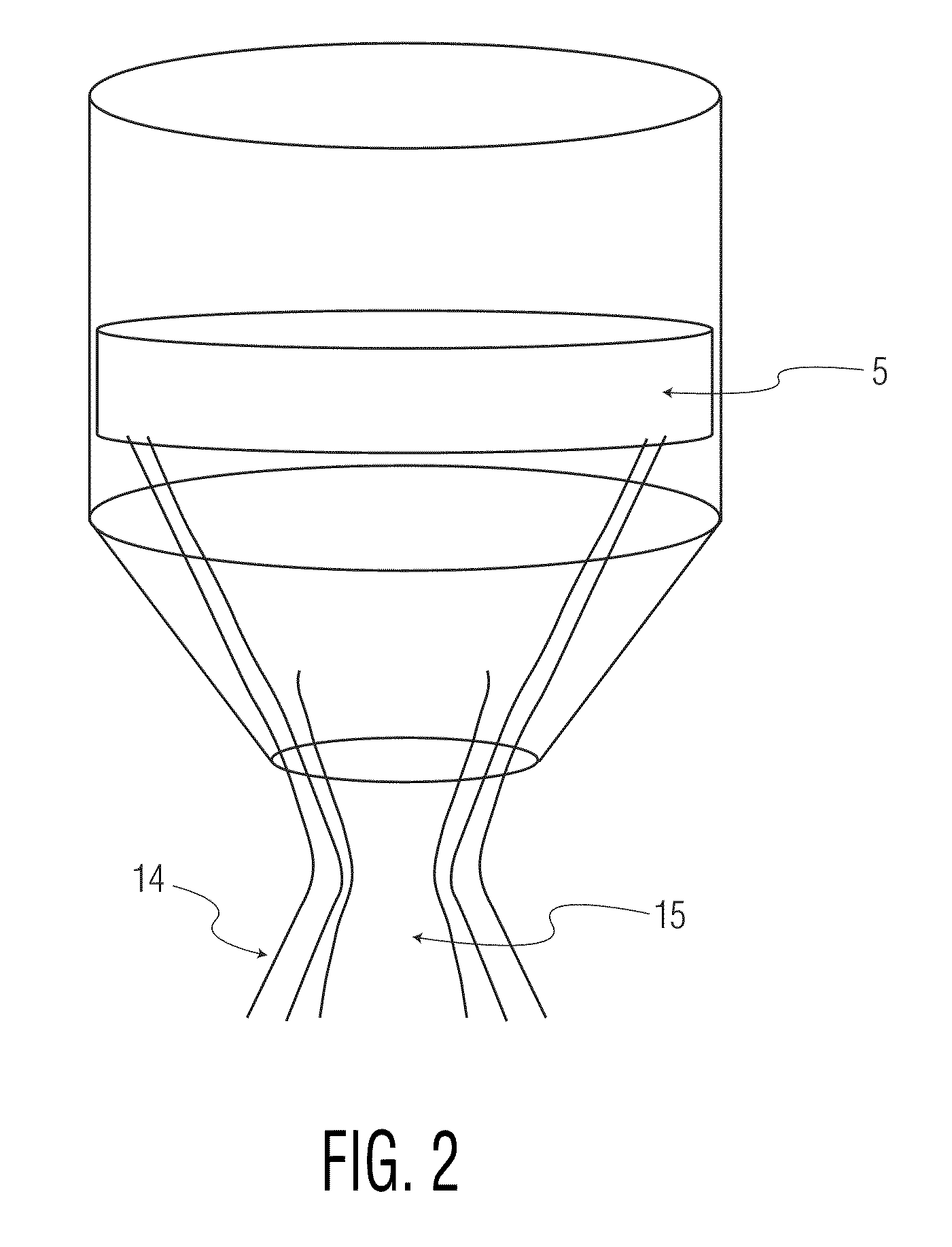
[0009]In a preferred embodiment of the present invention, the second portion is shaped as to match the acoustic profile of the ultrasound transducer. In other words, the tapered shape or outer surface between distal and proximal end of the second portion of the transducer preferably corresponds to a surface of equal intensity of the
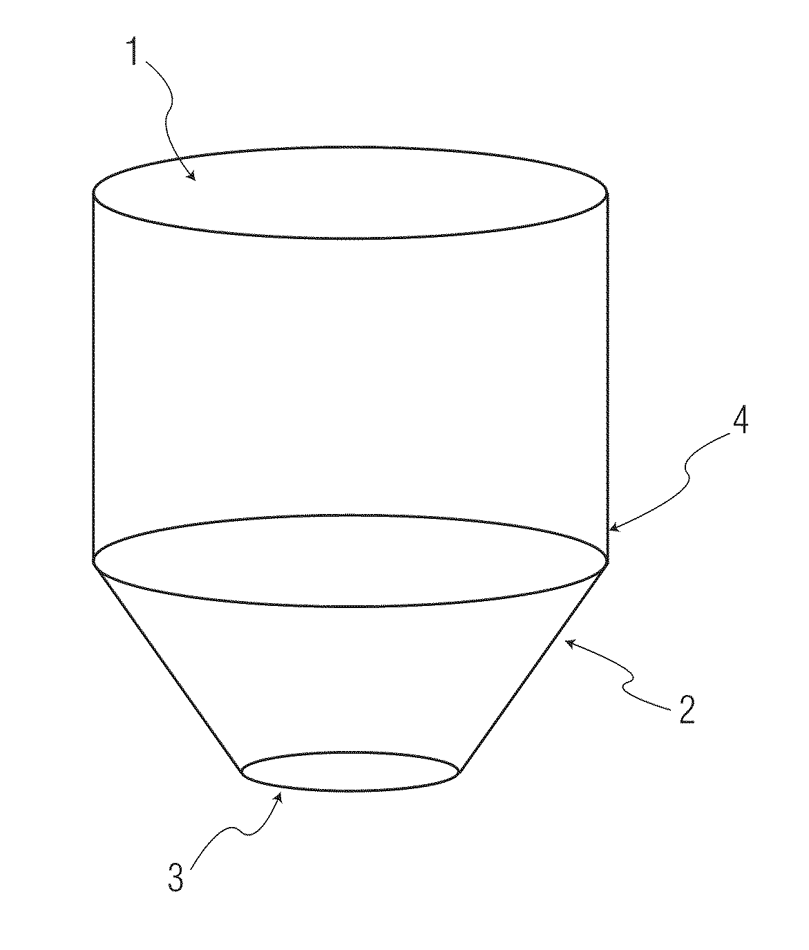
ultrasound beam profile, e.g., a −20 dB profile surface. In some embodiments of the present invention, the second portion of the standoff may be cone-shaped, the axis of
rotational symmetry being the direction of
sound propagation. The outer surface of the second portion between distal and proximal end may as well comprise a curved taper, the curvature being concave or convex. In particular, the angular
pitch or curvature of the taper is designed in order to match the transducer beam profile. This shape allows for an optimized focussing of the ultrasound close to the distal end of the standoff, while at the same time minimizing
acoustic reflection at the walls of the second portion.
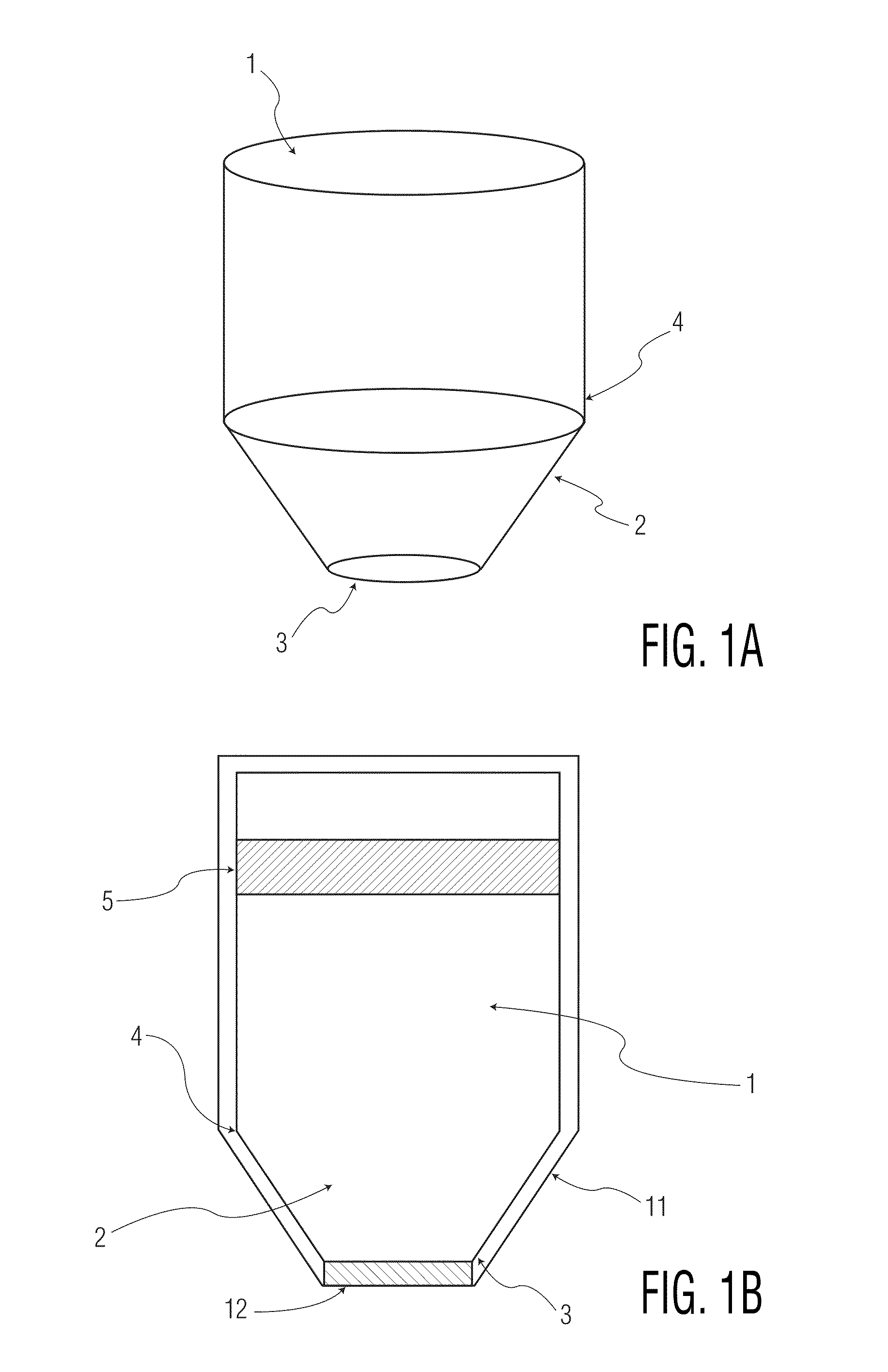
[0014]In another embodiment, the standoff further comprises a support element adapted to support the transducer, which is arranged at the proximal end of the first portion. Said support may be movable with respect to the second portion along the direction of
sound propagation and / or rotatable around the axis defined by the direction of sound propagation by use of a moving means. In order to allow for translations of the support element together with the transducer along the direction of sound propagation it is advantageous if at least the first portion consists of a
fluid coupling medium. This enables the user to adjust the ultrasound focus in the direction of sound propagation while the standoff stays in contact with the tissue to be imaged or treated. The envelope is designed to allow for movement of the support element and the transducer and to halt said movement just before reaching a position where the acoustic beam profile would interact with the tapered or curved surface of the second portion of the standoff. A focus adjustment would also be possible in case of
solid- or gel-like acoustic coupling media. However, in this case first portions of
varying thickness would have to be inserted in order to move the transducer with respect to the tip of the second portion.
[0015]The second portion is preferably closed by an acoustic window at the distal end, wherein said acoustic window is substantially transparent for ultrasound. The acoustic window may comprise a gel and / or a gel-like
solid. It may as well comprise a membrane made from, e.g., biaxially-oriented
polyethylene terephthalate (like Mylar™), a
thermoplastic elastomer (like Santoprene™), a
plastic wrap or the like. The window may be part of the envelope and ensures that the acoustic coupling medium stays within the standoff while at the same time allowing for basically unhindered ultrasound transmission. However, it may be advantageous if the membrane allows for minor leakage in order to wet the outside of the distal end of the second portion in order to improve coupling between standoff and tissue. Another way to improve this coupling is to provide an acoustic
sponge or gel container on the exterior portion of the acoustic window or on the outside of the distal end of the second portion. This as well provides a better acoustic contact between the tissues to be imaged or treated and the standoff. It may be especially helpful in case of rough or uneven tissue surfaces.
[0017]In a preferred embodiment of the present invention, the envelope enclosing the standoff is made of an optically transparent material like acrylic polymers such as
polymethyl methacrylate, polycarbonates, polysulfones, polystyrenes,
styrene-butadiene copolymers, cellulosis,
thermoplastic polyesters and glass to allow for
visual inspection of the interior of the standoff. This enables the user of the standoff to ensure that there is no accumulation of bubbles on the surface of the transducer. In some embodiments, the standoff may further comprise a means for gripping the standoff, e.g., a
handle or a shaped plastic.
[0018]The shape of the acoustic standoff is designed to allow for several advantages: It enables movement of the transducer relative to the second portion of the standoff along the main direction of sound propagation. The cone-like focusing is designed to start at a point where the cone shape substantially matches the acoustic field of the transducer thereby minimizing
acoustic reflection and ensuring that the user does not operate the transducer in a region where the beam is not transmitted to the tissue. The size of the acoustic window is chosen to match small structures, e.g. the
anatomy of a
small animal so that the point of contact with the animal is minimized. This design allows for much more accurate placement of the transducer / standoff pair using external morphological landmarks. In addition, the acoustic window may be designed to allow any imaging transducer placed with a therapy transducer to have an adequate imaging window into the animal. The initial placement of the therapy transducer may also be guided by
visual observation (or a
laser pointing device) of the targeted region through a therapeutic transducer centre hole and the acoustic window.
[0019]The shape of the standoff is also designed so that the amount of acoustic coupling fluid is minimized while still allowing for axial adjustment of the transducer so that superficial structures can be treated. The rigidity of the acoustic window and the standoff itself is a beneficial choice since this will allow removal of all weight of the standoff and transducer from, e.g., the animal. This ensures that the animal will not risk suffocation with insonification proceeds.

