Switched diverter circuits for minimizing heating of an implanted lead and/or providing EMI protection in a high power electromagnetic field environment

a technology of emi protection and diverter circuit, which is applied in the field of energy induced on implanted leads, can solve the problems of overheating of said lead or its associated electrode or overheating of the associated interface with body tissue, loss of cardiac pacemaking pulse capture, brain damage or multiple amputations

Inactive Publication Date: 2010-07-29
WILSON GREATBATCH LTD
View PDF101 Cites 69 Cited by
  • Summary
  • Abstract
  • Description
  • Claims
  • Application Information

AI Technical Summary

Benefits of technology

[0049]A switch may be associated with the implanted lead or the leadwire, for electrically opening the implanted lead or the leadwire without substantial degradation of the transfer to the energy dissipating surface of the high frequency energy induced on the implanted lead or the leadwire at the selected RF frequency or frequency band. In this case, the switch is disposed in series with the implanted lead or the leadwire. The diversion circuit extends from the lead or the leadwire to the energy dissipating surface and comprises a continuous permanently closed circuit. The switch disconnects the AIMD electronic circuits from the implanted lead or the leadwire during an MRI scan.
[0050]The diversion circuit may comprise a high pass filter which prevents low frequency gradient field-induced energy in the implanted lead or the leadwire from passing through the diversion circuit to the energy dissipating surface. The high pass filter may comprise a capacitor, a resistor in series with the capacitor, or an L-C trap filter.

Problems solved by technology

It has been documented that when this current becomes excessive, that overheating of said lead or its associated electrode or overheating of the associated interface with body tissue can occur.
There have been cases of damage to such body tissue which has resulted in loss of capture of cardiac pacemaking pulses, tissue damage, severe enough to result in brain damage or multiple amputations, and the like.
Compatibility of probes, catheters, cardiac pacemakers, implantable defibrillators and other types of active implantable medical devices with magnetic resonance imaging (MRI) and other types of hospital diagnostic equipment has become a major issue.
These antennas are not very efficient due to the damping effects of body tissue; however, this can often be offset by extremely high power fields (such as MRI pulsed fields) and / or body resonances.
Subjected to RF frequencies, the lead itself can exhibit complex transmission line behavior.
The effects of this heating are not readily detectable by monitoring during the MRI.
Such long term heating effects of MRI have not been well studied yet for all types of AIMD lead geometries.
There can also be localized heating problems associated with various types of electrodes in addition to tip electrodes.
Most experts still conclude that MRI for the pacemaker patient should not be considered safe.
It is well known that many of the undesirable effects in an implanted lead system from MRI and other medical diagnostic procedures are related to undesirable induced EMFs in the lead system and / or RF currents in its distal tip (or ring) electrodes.
This can lead to overheating of body tissue at or adjacent to the distal tip.
Excessive current at the distal electrode to tissue interface can cause excessive heating to the point where tissue ablation or even perforation can occur.
This can be life threatening for cardiac patients.
For neurostimulator patients, such as deep brain stimulator patients, thermal injury can cause permanent disability or also be life threatening.
Similar issues exist for spinal cord stimulator patients, cochlear implant patients and the like.
A very important and life-threatening problem is to be able to control overheating of implanted leads during an MRI procedure.
A major challenge for designing an L-C bandstop filter for human implant is that it must be very small in size, biocompatible, and highly reliable.
As the feedthrough capacitor charges up this voltage fall can create one of two problems.
First, the voltage induced on the lead system could directly capture the heart thereby creating a dangerously rapid heart rate which could then result in a dangerous ventricular arrhythmia.
For example, ventricular fibrillation can result in sudden death.
Another problem associated with too high of a value of a feedthrough capacitor at the input to the AIMD is that this R-C charging circuit can cause pulses to appear at the input sense amplifier (such as a cardiac pacemaker) such that the pacemaker would oversense or falsely interpret this input as a normal heartbeat.
In certain cases this can cause a demand pacemaker to inhibit (stop pacing).
For a pacemaker dependent patient this can lead to systole and be immediately life threatening.
In fact, in many measurements made by the inventors, temperature rises of over 30 degrees C. have been reduced to less than 3 degrees C. However, a secondary problem has been discovered.
In some cases, the inventors have measured temperature rises immediately proximal to the bandstop filters, which is undesirable.

Method used


Image

  • Switched diverter circuits for minimizing heating of an implanted lead and/or providing EMI protection in a high power electromagnetic field environment
  • Switched diverter circuits for minimizing heating of an implanted lead and/or providing EMI protection in a high power electromagnetic field environment
  • Switched diverter circuits for minimizing heating of an implanted lead and/or providing EMI protection in a high power electromagnetic field environment

Examples


Embodiment Construction

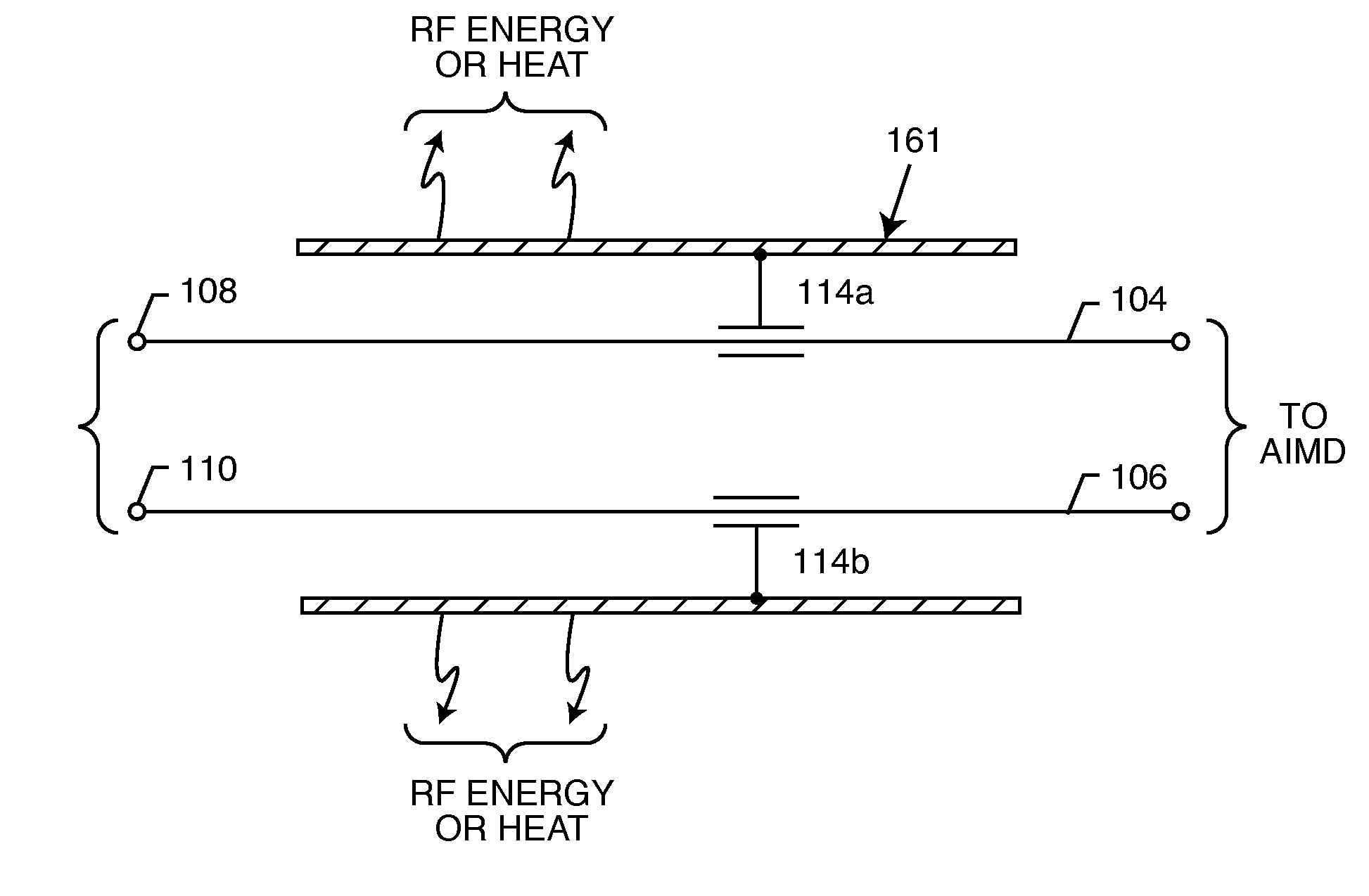
[0178]As shown in the drawings for purposes of illustration, the present invention resides in a tuned energy balanced system including a switched diverter circuit, for minimizing heating of an implanted lead and / or providing

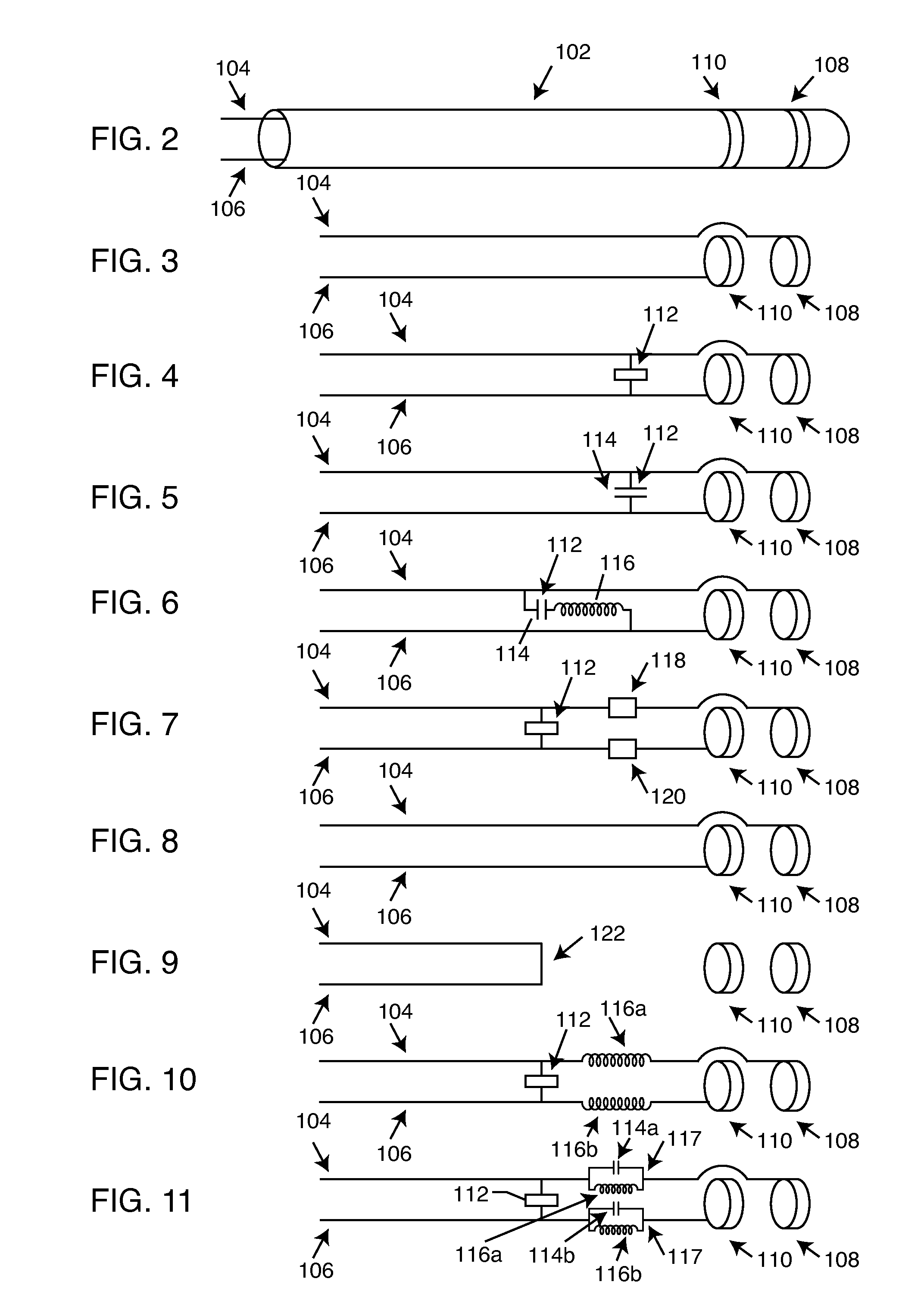
[0179]More particularly, the present invention resides in a switched diverter circuit comprising at least one switch for diverting energy in the implanted lead or a leadwire through the diversion circuit to the energy dissipating surface. In alternate embodiments, the switch is disposed between the implanted lead or the leadwire and the diversion circuit, or it is situated such that it electrically opens the implanted lead or the leadwire when diverting energy in the implanted lead or the leadwire through the diversion circuit to the energy dissipating surface. The switch may comprise a single or a multi-pole double throw or single throw switch.

[0180]In one preferred embodiment, the invention resides in a combination of bandstop filters placed at or near the dis...


PUM


Abstract

An energy management system that facilitates the transfer of high frequency energy induced on an implanted lead or a leadwire includes an energy dissipating surface associated with the implanted lead or the leadwire, a diversion or diverter circuit associated with the energy dissipating surface, and at least one non-linear circuit element switch for diverting energy in the implanted lead or the leadwire through the diversion circuit to the energy dissipating surface. In alternate configurations, the switch may be disposed between the implanted lead or the leadwire and the diversion circuit, or disposed so that it electrically opens the implanted lead or the leadwire when diverting energy through the diversion circuit to the energy dissipating surface. The non-linear circuit element switch is typically a PIN diode. The diversion circuit may be either a high pass filter or a low pass filter.

Description

BACKGROUND OF THE INVENTION[0001]This invention generally relates to the problem of energy induced on implanted leads during medical diagnostic procedures such as magnetic resonant imaging (MRI). Specifically, the radio frequency (RF) pulsed field of MRI can couple to an implanted lead in such a way that electromagnetic forces (EMFs) are induced in the lead. The amount of energy that is induced is related to a number of complex factors, but in general, is dependent upon the local electric field that is tangent to lead and the integral of the electric field strength along the lead. In certain situations, these EMFs can cause currents to flow into distal electrodes or in the electrode interface with body tissue. It has been documented that when this current becomes excessive, that overheating of said lead or its associated electrode or overheating of the associated interface with body tissue can occur. There have been cases of damage to such body tissue which has resulted in loss of c...

Claims


Application Information

Patent Timeline
Patent Type & Authority Applications(United States)
IPC IPC(8): A61B18/14A61N1/05
CPCA61B5/042A61N1/05A61B2018/00452A61B2018/00839A61B2019/5236A61N1/3718A61N2001/086G01R33/286G01R33/288H03H7/0107A61B5/04A61N1/08H03H7/1758H03H7/1766A61B5/7203A61B5/055A61B2090/374A61N1/086A61B5/283A61B5/24
Inventor JOHNSON, ROBERT SHAWNDABNEY, WARREN S.STEVENSON, ROBERT A.WILLIAMS, CHRISTOPHER MICHAELMOSCHIANO, HOLLY NOELLEBRAINARD, SCOTTKAISER, DANIEL ROBERTHALPERIN, HENRY R.LARDO, ALBERT C.KELLEY, SCOTT W.
Owner WILSON GREATBATCH LTD
Why Eureka
Try Eureka