Method for cooling hot strip

a hot strip and cooling technology, applied in heat treatment apparatus, shaping tools, furnaces, etc., can solve the problems of temperature deviation, limited effect, etc., and achieve the effect of reducing the amount of cooling water, preventing thermal instability in cooling, and lowering the precision with which the cooling end temperature can be controlled

Active Publication Date: 2010-08-05
JFE STEEL CORP
View PDF1 Cites 20 Cited by
  • Summary
  • Abstract
  • Description
  • Claims
  • Application Information

AI Technical Summary

Benefits of technology

[0020]In the method described in Patent Document 1, the temperature variation due to residual cooling water on the upper side of a strip can be reduced. However, entering the temperature range of transition boiling where thermal instability in cooling occurs is not prevented by simply supplying cooling water to the lower side of the strip. Therefore, the precision with which the cooling end temperature can be controlled is lowered.
[0025]An object of the present invention is to provide a method for solving the problems of the related art described above with less facilities and processing costs, and specifically, a method for cooling a hot strip in which the temperature variation of a strip after cooling is controlled to be small and a cooling end temperature can be precisely controlled particularly when the hot strip is cooled to the temperature range of 500° C. or less.
[0026]The inventors of the present invention paid attention to the fact that the higher a water flow rate of cooling water supplied to a hot strip was, the higher a transition boiling initiation temperature and a nucleate boiling initiation temperature became; and found that entering the temperature range of transition boiling could be completely prevented to avoid thermal instability in cooling resulting from the transition boiling, by stopping cooling at a strip temperature that is higher than a transition boiling initiation temperature in the cooling step (first cooling step) on the high temperature side, and then conducting cooling with the cooling water having a cooling water flow rate that causes nucleate boiling in the cooling step (second cooling step) on the low temperature side.
[0037]In the cooling method of the present invention, entering the temperature range of transition boiling can be prevented to completely avoid thermal instability in cooling resulting from the transition boiling. Thus, the temperature variation of a strip after cooling is controlled to be small and a cooling end temperature can be precisely controlled. In particular, the cooling end temperature can be precisely controlled when the hot strip is cooled to the temperature range of 500° C. or less, which has been difficult in the related art. Regarding a hot strip coiled at 500° C. or less, there has been the variation of material properties such as strength and ductility in the related art. However, the variation of material properties is reduced and the material properties can be controlled within a narrow range.

Problems solved by technology

However, the methods of the related art described above include the following practical problems.
However, entering the temperature range of transition boiling where thermal instability in cooling occurs is not prevented by simply supplying cooling water to the lower side of the strip.
In the method described in Patent Document 2, although the transition boiling initiation temperature can be shifted to the low temperature side by using hot water, the effect is limited.
Moreover, the effect of the residual cooling water on the strip is not taken into account, which inevitably causes temperature deviation.
However, the gas cooling has a cooling performance lower than water cooling by one or two orders of magnitude.
Therefore, the cooling rate is significantly low and desired material properties cannot be obtained.
The low cooling rate by the gas cooling also requires a very long and large cooling apparatus for run out cooling of a hot strip.
It is quite difficult to realize this method.

Method used


Image

  • Method for cooling hot strip
  • Method for cooling hot strip
  • Method for cooling hot strip

Examples


invention example 1

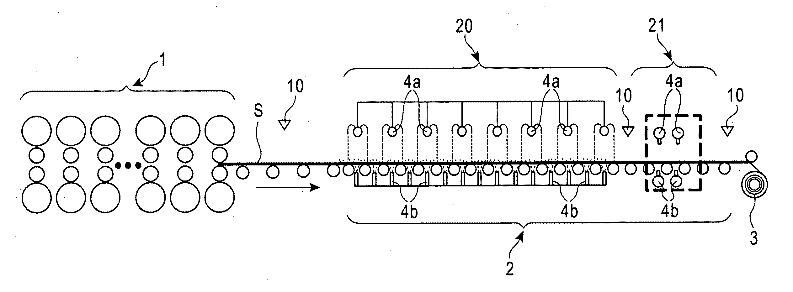
[0099]At the first run out table 20, the rolled hot strip was cooled to 550° C. with cooling water of 30° C. At the second run out table 21, the cooling water was then supplied by the jet cooling to the upper side of the strip from the two groups of round type jet nozzles A1 and A2 as shown in FIG. 5, while obliquely facing the strip in a strip processing line direction. The cooling water was also supplied by the spraying cooling to the lower side of the strip. The cooling water used at the second run out table 21 had a temperature of 30° C. and a water flow rate of 2500 L / min.m2 at both the upper and lower sides of the strip and the velocity at which the cooling water was ejected on the upper side of the strip was 4 m / sec.

[0100]In this invention example, the average temperature in the longitudinal direction of the strip after cooling was 302° C., which was substantially as desired. The temperature deviation of 50° C. in the longitudinal direction of the strip was also within the de...

invention example 2

[0101]At the first run out table 20, the rolled hot strip was cooled to 550° C. with cooling water of 30° C. At the second run out table 21, the cooling water was then supplied by the jet cooling to the upper side of the strip from the two groups of round type jet nozzles A1 and A2 as shown in FIG. 5, while obliquely facing the strip in a strip processing line direction. The cooling water was also supplied by the spraying cooling to the lower side of the strip. The cooling water used at the second run out table 21 had a temperature of 30° C. and a water flow rate of 3000 L / min.m2 at both the upper and lower sides of the strip and the velocity at which the cooling water was ejected on the upper side of the strip was 4 m / sec.

[0102]In this invention example, the average temperature in the longitudinal direction of the strip after cooling was 303° C., which was substantially as desired. The temperature deviation of 40° C. in the longitudinal direction of the strip was also within the de...

invention example 3

[0103]At the first run out table 20, the rolled hot strip was cooled to 550° C. with cooling water of 30° C. At the second run out table 21, the cooling water was then supplied by the jet cooling to the upper side of the strip from the two groups of round type jet nozzles A1 and A2 as shown in FIG. 5, while obliquely facing the strip in a strip processing line direction. The cooling water was also supplied by the spraying cooling to the lower side of the strip. The cooling water used at the second run out table 21 had a temperature of 30° C. and a water flow rate of 2500 L / min.m2 at both the upper and lower sides of the strip and the velocity at which the cooling water was ejected on the upper side of the strip was 7 m / sec.

[0104]In this invention example, the average temperature in the longitudinal direction of the strip after cooling was 297° C., which was substantially as desired. The temperature deviation of 38° C. in the longitudinal direction of the strip was also within the de...


PUM

PropertyMeasurementUnit
temperatureaaaaaaaaaa
velocityaaaaaaaaaa

Abstract

A method for cooling a hot strip with less facilities and processing costs in which the temperature variation of a strip after cooling is controlled to be small and a cooling end temperature can be precisely controlled particularly when the hot strip is cooled to the temperature range of 500° C. or less is provided. The method for cooling a hot strip, which is obtained after a hot rolling process, by bringing cooling water into contact with the hot strip, includes a first cooling step and a subsequent second cooling step. In this method, cooling is stopped at a strip temperature that is higher than a transition boiling initiation temperature in the first cooling step, and the cooling is conducted using the cooling water having a water flow rate that causes nucleate boiling in the subsequent second cooling step. Entering the temperature range of transition boiling can be completely prevented to avoid thermal instability in cooling resulting from the transition boiling, and the temperature variation of the strip after cooling is controlled to be small while the cooling end temperature can be precisely controlled.

Description

TECHNICAL FIELD [0001]The present invention relates to a method for cooling a hot strip after hot rolling by bringing cooling water into contact with the hot strip, and in particular, to a method for cooling a hot strip in which a cooling end temperature can be precisely controlled when the hot strip is cooled to 500° C. or less.BACKGROUND ART[0002]In a hot rolling process for manufacturing a hot strip, a slab heated to a high temperature is rolled so as to have a desired size and desired material properties, and then cooled with water on a run out table. The purpose of the water cooling is to obtain the desired material properties such as strength and ductility by mainly controlling the precipitates of the strip and the transformation structure of the strip. In particular, precisely controlling a cooling end temperature is significantly important to achieve the desired material properties without causing variation therefrom.[0003]Although water, which is inexpensive, is often used ...

Claims


Application Information

Patent Timeline
Patent Type & Authority Applications(United States)
IPC IPC(8): B21D37/16
CPCB21B45/0218B21B37/76B21B45/02C21D11/005C21D9/46C21D9/52C21D9/573C21D8/0263
Inventor UEOKA, SATOSHIKUROKI, TAKASHINISHIURA, NOBUO
Owner JFE STEEL CORP
Why Eureka
Try Eureka