
Method for producing organic electroluminescence element and organic electroluminescence element

a technology of electroluminescence element and organic electroluminescence element, which is applied in the direction of coating, chemical vapor deposition coating, plasma technique, etc., can solve the problems of uniform light emission, inability to obtain sufficient durability, and decrease in the drive voltage, so as to achieve the effect of reducing the durability

Active Publication Date: 2010-08-12
UDC IRELAND
View PDF36 Cites 12 Cited by
  • Summary
  • Abstract
  • Description
  • Claims
  • Application Information

AI Technical Summary

Benefits of technology

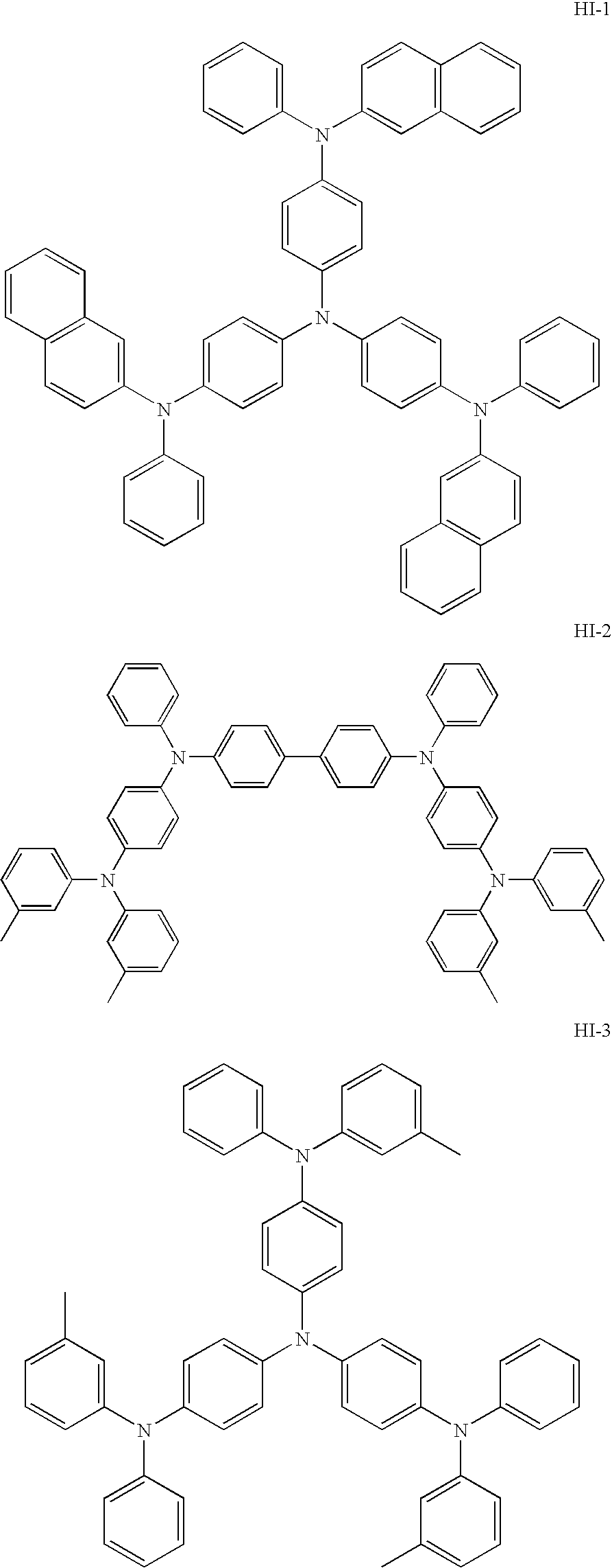
[0014]The present inventor conducted extensive studies to solve the above existing problems, and have found that (1) when a non-oxidizing gas such as argon gas, nitrogen gas, hydrogen gas and deuterium gas is used, the work function of an element treated therewith becomes small as compared with the case where oxygen gas is used and the element requires a higher drive voltage, but the durability thereof is improved, and (2) the increase in drive voltage can be suppressed through p-doping of the hole-injection layer.
[0027]The present invention can provide a method for producing an organic electroluminescence element which method can provide an element whose drive voltage is low, the increase of which in voltage during driving is suppressed, and the decrease of which in durability due to oxidizing gas is suppressed; and an organic electroluminescence element produced by the method. These can solve the existing problems.

Problems solved by technology

As a result, no barrier with respect to HOMO level can be attained in an organic film on the electrode, leading to decrease in necessary drive voltage.
Without surface treatment, stain on the electrode surface is not removed, potentially resulting in that sufficient durability cannot be obtained, for example, a short circuit occurs between the electrodes, and ununiform light emission is observed on a light-emitting surface.
However, when the electrode is subjected to surface treatment using oxygen, sufficient durability cannot be necessarily attained.
However, the elements formed through the surface treatments disclosed in these literatures disadvantageously require a higher drive voltage and involve a greater increase in voltage during driving than those formed through surface treatment using oxygen.
In particular, when a reducing gas such as hydrogen gas and deuterium gas is used, the work function of the electrode becomes small.
As a result, the hole-injection barrier with respect to an organic film becomes large, resulting in that the formed element requires a high drive voltage.
Without surface treatment, a short circuit occurs between the electrodes, and ununiform light emission occurs.
Thus, at present, there cannot still be obtained a satisfactorily high-performance organic electroluminescence element whose drive voltage is low, whose service life is long, and whose durability is good.

Method used


Image

  • Method for producing organic electroluminescence element and organic electroluminescence element
  • Method for producing organic electroluminescence element and organic electroluminescence element
  • Method for producing organic electroluminescence element and organic electroluminescence element

Examples


examples

[0142]The present invention will next be described by way of examples, which should not be construed as limiting the present invention thereto.

example 1

[0160]The procedure of Comparative Example 5 was repeated, except that the hole-injection layer was doped with an electron-accepting dopant (F4TCQN) in an amount of 0.3% by mass with respect to the material of the hole-injection layer, to thereby produce an organic electroluminescence element of Example 1.

example 2

[0161]The procedure of Comparative Example 6 was repeated, except that the hole-injection layer was doped with an electron-accepting dopant (F4TCQN) in an amount of 0.3% by mass with respect to the material of the hole-injection layer, to thereby produce an organic electroluminescence element of Example 2.


PUM

PropertyMeasurementUnit
current densityaaaaaaaaaa
depthaaaaaaaaaa

Abstract

A method for producing an organic electroluminescence element, the method including subjecting an anode to a surface treatment using at least one non-oxidizing gas, and forming a p-doped hole-injection layer on a surface of the anode subjected to the surface treatment.

Description

BACKGROUND OF THE INVENTION[0001]1. Field of the Invention[0002]The present invention relates to a method for producing an organic electroluminescence element and to an organic electroluminescence element produced by the method.[0003]2. Description of the Related Art[0004]In order for organic electroluminescence elements to be widely put into practical use, development has been demanded for a high-performance organic electroluminescence element whose drive voltage is low, whose service life is long, and whose durability is good.[0005]In the production of an organic electroluminescence element, an electrode (e.g., an ITO film) constituting the organic electroluminescence element is generally subjected to surface treatment through oxygen plasma treatment or UV-ozone treatment. By virtue of this treatment, organic matter on the electrode is decomposed and washed away. As a result, no barrier with respect to HOMO level can be attained in an organic film on the electrode, leading to decr...

Claims


Application Information

Patent Timeline
Patent Type & Authority Applications(United States)
IPC IPC(8): H01L51/10B05D5/06C23C16/44
CPCH01L51/5052H01L51/5088H01L51/5016H01L51/002H01L51/0081H01L51/5206H10K71/30H10K85/324H10K50/11H10K2101/10H10K50/155H10K50/17H10K50/81
Inventor SATO, TASUKU
Owner UDC IRELAND
Learn More