

Polarizing element and method for manufacturing the same, projection type display, liquid crystal device, and electronic apparatus
- Summary
- Abstract
- Description
- Claims
- Application Information
AI Technical Summary
Benefits of technology
Problems solved by technology
Method used
Image

Examples
first embodiment
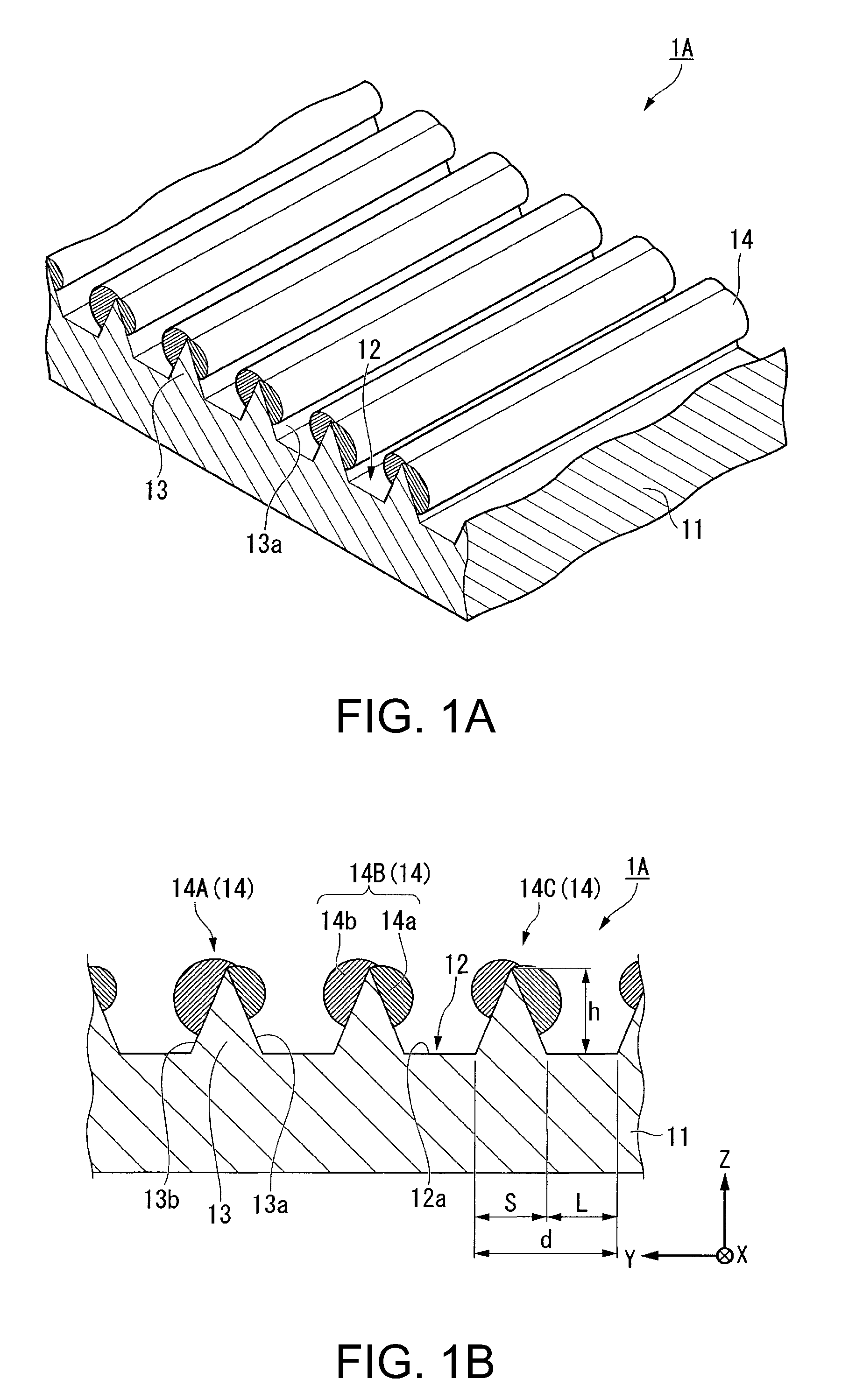
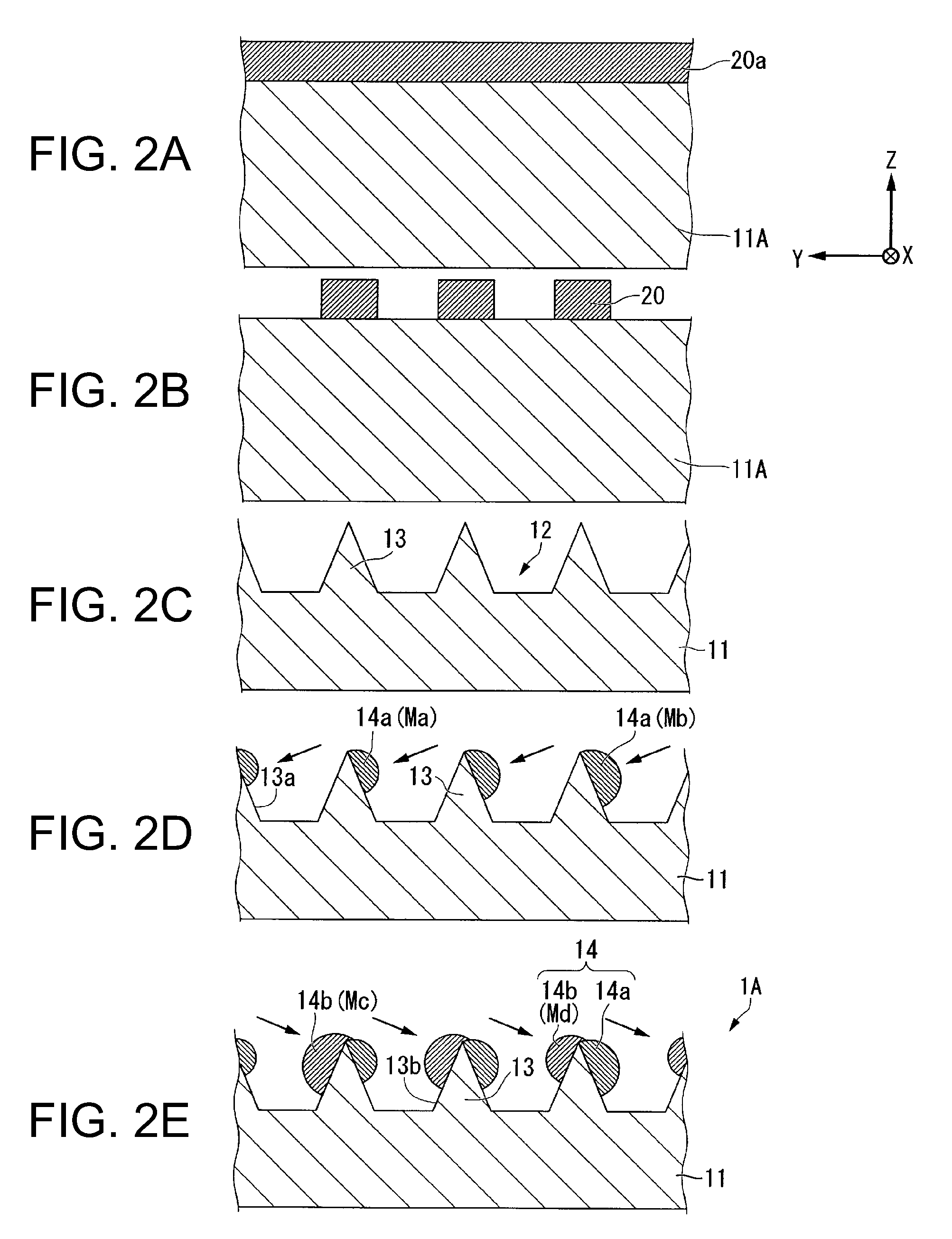
[0073]A polarizing element and a method for manufacturing a polarizing element according to a first embodiment will now be described with reference to the accompanying drawings. FIGS. 1A and 1B are schematic views of a polarizing element 1A of the first embodiment. FIG. 1A is a partial perspective view. FIG. 1B is a partial cross-sectional view of the polarizing element 1A taken along a YZ plane.
[0074]In the following descriptions, an XYZ coordinate system is established, and a positional relation of elements will be described with reference to this system. Here, a predetermined direction on a level surface is indicated as an X-axis direction; a direction perpendicular to the X-axis direction on the level surface is indicated as a Y-axis direction; and a direction perpendicular to both X-axis and Y-axis directions is indicated as a Z-axis direction. In the embodiment, an extending direction of metal thin wires is set to be in the X-axis direction, and an arrangement axis of the meta...
second embodiment
[0142]FIGS. 15A and 15B are explanatory views of a polarizing element 1B according to a second embodiment. The polarizing element 1B of the second embodiment is partially in common with the polarizing element 1A of the first embodiment. The polarizing element 1B differs in that a protective film covers the surfaces of the metal thin wires 14 of the polarizing element 1A. Therefore, in the second embodiment, components that are common with those of the first embodiment will be affixed with the same numerals, and detailed descriptions thereof will be omitted.
[0143]As shown in FIG. 15A, the polarizing element 1B has a protective film 16 covering the surfaces of the metal thin wires 14 and the substrate 11. The protective film 16 is a light transmissive insulation film such as a silicon oxide film. The protective film 16 includes a first protective film 16a, a second protective film 16b, and a third protective film 16c. The first protective film 16a covers both side surfaces of the prot...
examples
[0193]Examples of the invention will now be described below. The following examples show an evaluation based on simulation analysis to confirm the effects of the invention.
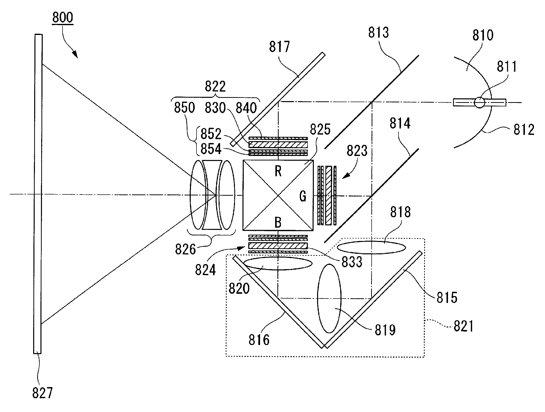
[0194]The evaluation is also based on an assumption that the polarizing element is used as a polarizing element for a light valve of a liquid crystal projector. The polarizing element has high thermal resistance since it is made of an inorganic material, and can preferably be applied to a pre-polarizing plate of a liquid crystal projector including a high power output light source.
[0195]Such a pre-polarizing plate needs to have a high optical transmittance with respect to TM light (Transverse Magnetic) and to well transmit the TM light. On the other hand, the pre-polarizing plate does not need to have a high optical absorptance with respect to TE light (Transverse Electric) since two polarizing elements work together to absorb the TE light as described above. Specifically, the following ranges are acceptable in pr...
PUM
| Property | Measurement | Unit |
|---|---|---|
| Fraction | aaaaa | aaaaa |
| Volume | aaaaa | aaaaa |
| Light | aaaaa | aaaaa |
Abstract
Description
Claims
Application Information