

Plasma processing apparatus
a processing apparatus and plasma technology, applied in the direction of electrical apparatus, electric discharge tubes, basic electric elements, etc., can solve the problem of inability to prevent this shielding via a static magnetic field
- Summary
- Abstract
- Description
- Claims
- Application Information
AI Technical Summary
Benefits of technology
Problems solved by technology
Method used
Image


Examples
embodiment 1
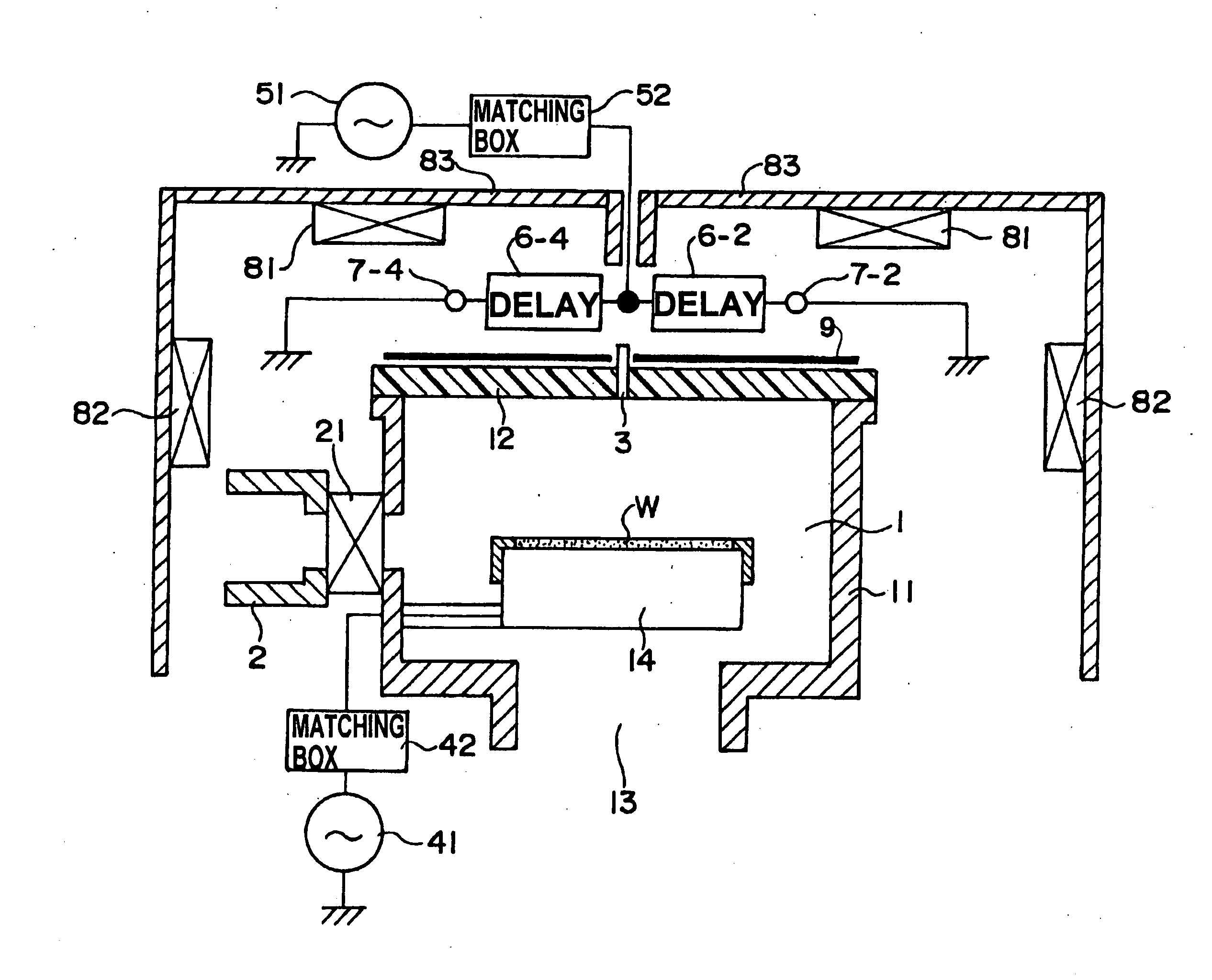
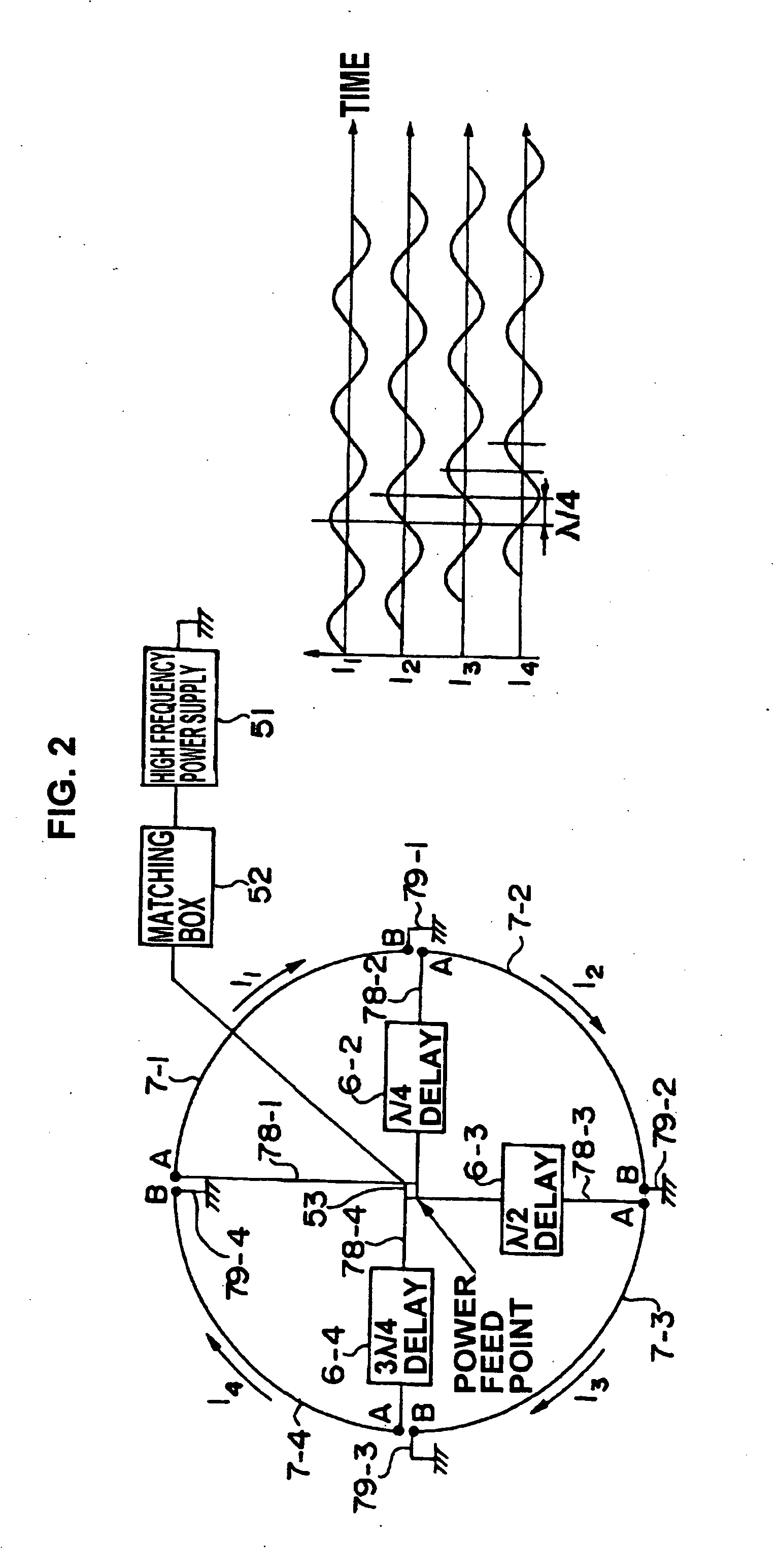
[0095]With reference to FIG. 2, a first embodiment of the plasma processing apparatus according to the present invention will be described. According to this embodiment, as shown in the left side of FIG. 2 showing a top view of FIG. 1, the high frequency induction antenna 7 is divided into high frequency induction antenna elements 7-1 through 7-4, formed by dividing the antenna into n=4 (n being an integer of n 2) parts on a single circumference. The power feed ends A or the grounded ends B of the respective high frequency induction antenna elements 7-1, 7-2, 7-3 and 7-4 are separated by angle 360° / 4 (360° / n) in the clockwise direction, and high frequency current is supplied from the plasma generating high frequency power supply 51 via the plasma generating matching box 52 through the feeding point 53 via the respective power feed ends A to the respective high frequency induction antenna elements 7-1, 7-2, 7-3 and 7-4. In the present embodiment, the respective high frequency inducti...
embodiment 2
[0123]A second example of the shape of the vacuum chamber top member will be described with reference to FIG. 14 as a second embodiment. In FIG. 14, the structure of the plasma processing apparatus other than the shape of the vacuum processing chamber top member 12 is the same as that of the plasma processing apparatus of FIG. 1, and the same components are denoted by the same reference numbers, so that the descriptions thereof are omitted. The vacuum processing chamber top member 12 of FIG. 1 is composed of a planar (disk-shaped) insulating member, but according to the present example, the vacuum processing chamber top member 12 formed of insulating material is formed in the shape of a hollow hemispherical shape or dome shape, which is airtightly fixed to the top of the cylindrical vacuum chamber 11 as illustrated to constitute the vacuum processing chamber 1. According to this arrangement, as shown in FIG. 18C, a plasma generating region is formed on the ECR plane.
embodiment 3
[0124]A third example of the shape of the vacuum chamber top member will be described with reference to FIG. 15 as a third embodiment. In FIG. 15, the structure of the plasma processing apparatus other than the shape of the vacuum processing chamber top member 12 is the same as that of the plasma processing apparatus of FIG. 1, and the same components are denoted by the same reference numbers, so that the descriptions thereof are omitted. In the present example, the vacuum processing chamber top member 12 formed of insulating material has a shape in which the top portion of a hollow circular cone is cut off to form a flat ceiling and a space is formed in the interior thereof, which is airtightly fixed to the top of the cylindrical vacuum chamber 11 as illustrated to form the vacuum processing chamber 1. In the specification, this shape of the vacuum chamber top member 12 is called a trapezoidal rotated body. According to this arrangement, a plasma generation region P is formed on th...
PUM
| Property | Measurement | Unit |
|---|---|---|
| impedance | aaaaa | aaaaa |
| resistivity | aaaaa | aaaaa |
| skin depth | aaaaa | aaaaa |
Abstract
Description
Claims
Application Information