Cellulose Ester Film, Light Diffusing Film, Polarizing Plate, and Liquid Crystal Display

a technology of light diffusing film and cellulose ester, which is applied in the direction of instruments, other domestic objects, transportation and packaging, etc., can solve the problems of insufficient, difficult to obtain the currently-required film, and more the above-mentioned characteristics, etc., to achieve excellent dimensional stability of polarizing plate, excellent more in optical isotropy, and high flatness

Active Publication Date: 2010-09-16
KONICA MINOLTA OPTO
View PDF2 Cites 17 Cited by
  • Summary
  • Abstract
  • Description
  • Claims
  • Application Information

AI Technical Summary

Benefits of technology

[0025]According to the present invention, it becomes possible to provide a cellulose ester film excellent in the dimensional stability of a polarizing plate, the curl characteristics of a polarizing plate, and the surface nature of a polarizing plate, further to provide a light diffusing film excellent more in optical isotropy, high flatness, smooth surface, little curl, and good plane quality by use of the cellulose ester film, a polarizing plate and a liquid crystal display device.

Problems solved by technology

However, it turned out that only with the addition of ethylenic polymer, it is difficult to obtain a currently-required film in which retardation in the thickness direction is small and a polarizing plate excellent in the curl characteristics of a polarizing plate and the surface nature of a polarizing plate.
Further, it turned out that the more the ethylenic polymer is added in order to reduce retardation, the more the above-mentioned characteristics deteriorate.
Moreover, although various light diffusing films are proposed by, for example, Patent documents 3 to Patent document 8, these proposed light diffusing films have a complicated structure and is not sufficient as a light diffusing film having good optical characteristics and plane quality.

Method used


Image

  • Cellulose Ester Film, Light Diffusing Film, Polarizing Plate, and Liquid Crystal Display
  • Cellulose Ester Film, Light Diffusing Film, Polarizing Plate, and Liquid Crystal Display
  • Cellulose Ester Film, Light Diffusing Film, Polarizing Plate, and Liquid Crystal Display

Examples


example 1

Preparation of Polymer

(Synthesis of AC1 to AC6: Polymer X)

[0346]Into a glass flask equipped with an agitator, 2 dropping funnels, a gas introducing tube and a thermometer, 40 g of a mixture of monomers of the types and ratios shown in Table 1, 3 g of mercapto propionic acid being a chain transfer agent and 30 g of toluene were charged, and the temperature was increased to 90° C. Subsequently, 60 g of a mixture of monomers of the types and ratios shown in Table 1 were added by dropping over a 3 hour period through one of the dropping funnels and at the same time, 0.6 g of azobisisobutylonitryl dissolved in 14 g of toluene was added by dropping over a 3 hour period through another one of the dropping funnels. Subsequently, 0.6 g of azobisisobutylonitryl dissolved in 56 g of toluene was further added by dropping over a 2 hour period and the reaction was continued for another 2 hours, whereby AC1 being polymer X was obtained. Next, the same synthesis as that for AC1 was conducted except...

example 2

[0408]By use of polarizing plates 1 to 34 produced in Example 1, the following liquid crystal displays were produced.

>

[0409]Liquid crystal panels to conduct view angle measurement were produced in the following ways, and the characteristics as a liquid crystal display were evaluated.

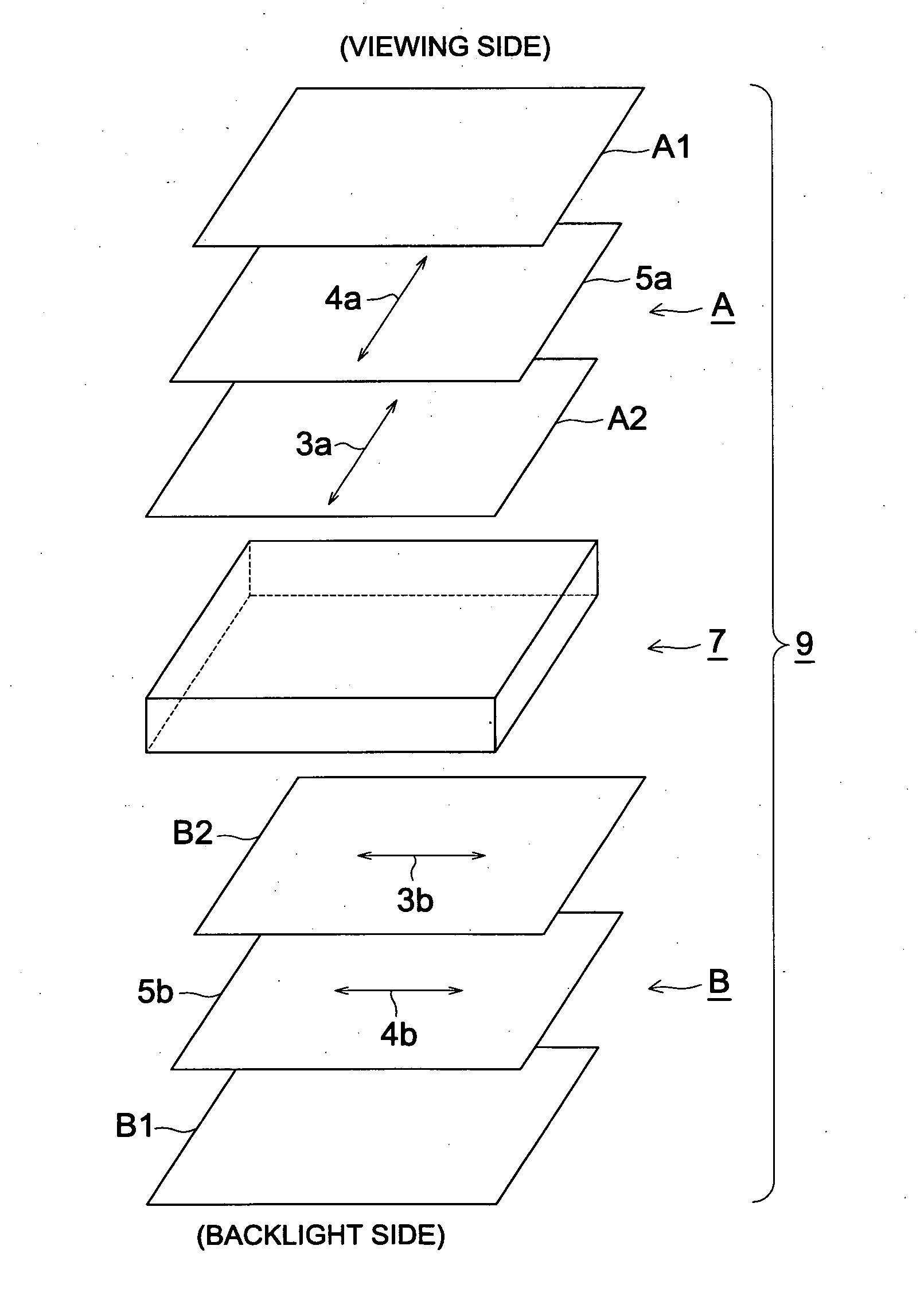
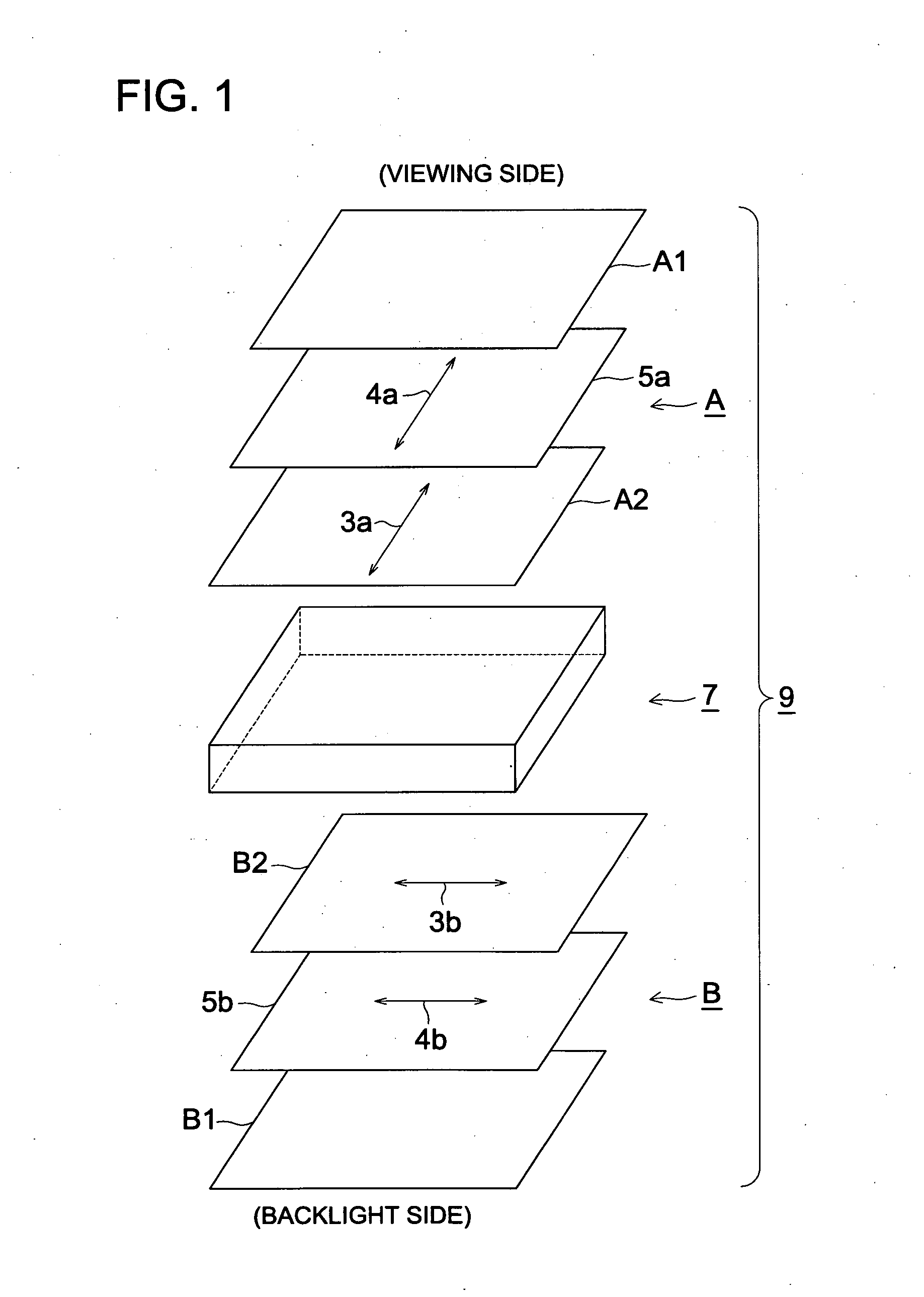
[0410]Only the polarizing plate pasted previously at the viewing side (observer side) of Hitachi liquid crystal television Wooo W17-LC50 being an IPS mode type liquid crystal display was removed, and the above produced Polarizing plates 1 to 32 were pasted to the glass plane of the liquid crystal cell, respectively.

[0411]At that time, the pasting direction of the polarizing plates was such that the absorption axis of the polarizing plates was oriented to the same direction of that of the previously pasted polarizing plate and the above produced cellulose ester films 1-32 were arranged at the viewing side, whereby Liquid crystal displays 1-32 were produced.

[0412]Furthermore, in the constitution of the liq...

example 3

[0420]Liquid crystal devices were produced as same as those in Example 2 except that Hitachi liquid crystal television Wooo W32-L7000 being a FFS mode type liquid crystal display was used in place of Hitachi liquid crystal television Wooo W17-LC50 being an IPS mode type liquid crystal display used in Example 1, and the same evaluation as that in Example 2 was conducted. As a result, the same results as those in Example 2 were obtained and the liquid crystal display device according to the present invention had an excellent visibility.


PUM

PropertyMeasurementUnit
particle sizeaaaaaaaaaa
RHaaaaaaaaaa

Abstract

Disclosed is a cellulose ester film which, when used in a polarizing plate, can impart excellent dimensional stability, curling properties and surface properties to the polarizing plate. Also disclosed is a light-scattering-film, a polarizing plate or a liquid crystal display element which is produced by using the cellulose ester film, and therefore has more excellent optical anisotropy, higher surface properties and a smoother surface, causes less curling, and has good surface quality. The cellulose ester film comprises 1 to 50% by mass (inclusive) of microparticles having an average particle diameter of 1 to 400 nm (inclusive) and a compound showing negative birefringence in the direction of drawing, and has a retardation value (R0) defined by the equation (I) of 0 to 5 nm (inclusive) and a retardation value (Rt) defined by the equation (II) of −10 to 20 nm (inclusive), both measured at 23° C. and 55% RH: Equation (I): R0=(nx−ny)×d; and Equation (II): Rt=[(nx+ny) / 2×nz]×d.

Description

TECHNICAL FIELD[0001]The present invention relates to a cellulose ester film, a light diffusing film, a polarizing plate, and a liquid crystal display.BACKGROUND ART[0002]With the high performance and high definition of a liquid crystal display, as a polarizing plate protective film used for a polarizing plate, the polarizing plate protective film is required to have a performance durable to a severe environmental variation in terms of the dimensional stability of a polarizing plate, the curl characteristics of a polarizing plate, and the surface nature of a polarizing plate.[0003]As a polarizing plate protective film of the liquid crystal display used generally at present, a film whose material is cellulose is used. As for a cellulose ester film, generally, a solution casting film forming method is taken from viewpoints of securement of flatness. Therefore, in the solution casting process, since a film expands to a thickness direction with evaporation of a solvent, the refractive i...

Claims


Application Information

Patent Timeline
Patent Type & Authority Applications(United States)
IPC IPC(8): C09K19/02B32B5/00
CPCC08J5/18Y10T428/105C08K5/103C08L1/10C08L33/08G02B5/3041G02B5/3083G02F1/133528G02F1/133634G02F2201/50C08J2301/10Y10T428/25Y10T428/10C08L2666/26C09K2323/035C09K2323/00C08L33/00G02F1/1335
Inventor SUZUKI, SHINICHIROTAKIMOTO, MASATAKA
Owner KONICA MINOLTA OPTO
Why Eureka
Try Eureka