Lubricating Oil Composition

Inactive Publication Date: 2010-10-07
HARTLEY ROLFE J +1
View PDF7 Cites 6 Cited by
  • Summary
  • Abstract
  • Description
  • Claims
  • Application Information

AI Technical Summary

Benefits of technology

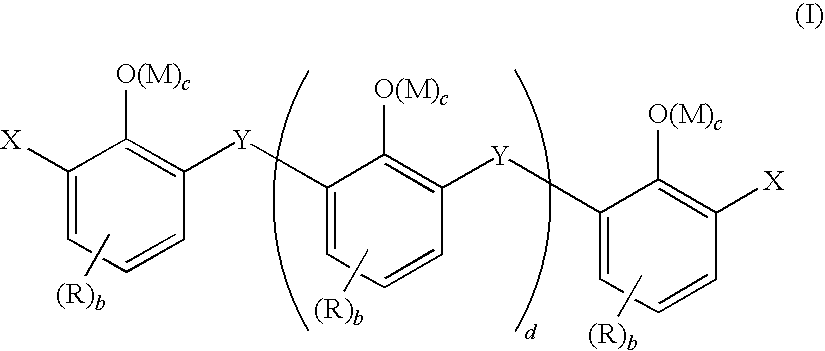
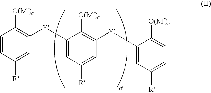
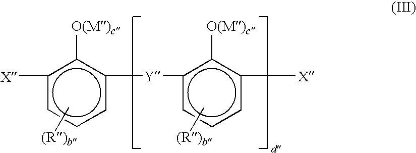
[0007]In accordance with a first aspect of the present invention, there is provided a lubricating oil composition which provides improved performance, particularly in diesel engines provided with exhaust gas recirculation (EGR) systems, and more particularly in diesel engines equipped with condensed EGR systems, which lubricating oil comprises a major amount of oil of lubricating viscosity, and minor amounts of (a) a viscosity modifier comprising one or more block copolymers of hydrogenated poly(monovinyl aromatic hydrocarbon) and poly(conjugated diene) and (b) one or more detergents comprising one or more optionally substituted bridged hydrocarbyl phenol condensates, or metal salts thereof.
[0008]In accordance with a second aspect of the present invention, there is provided a method of reducing soot-induced viscosity increase in lubricating oils for engines, particularly in diesel engines provided with exhaust gas recirculation (EGR) systems, and more particularly in diesel engines equipped with condensed EGR systems, which method comprises the step of formulating the lubricating oil composition with a combination of the viscosity modifier and detergent of the first aspect, lubricating the crankcase of the engine with the formulated lubricating oil composition and operating the engine.
[0009]In accordance with a third aspect of the present invention, there is provided the use of the combination of the viscosity modifier and the detergent of the first aspect to reduce the soot-induced viscosity increase of a lubricating composition for the lubrication of an engine, particularly in diesel engines provided with exhaust gas recirculation (EGR) systems, and more particularly in diesel engines equipped with condensed EGR systems during use.

Problems solved by technology

In the presence of these acids, it has been found that soot levels in lubricating oil compositions build rapidly, and that under said conditions, the kinematic viscosity (kv) of lubricating oil compositions increase to unacceptable levels, even in the presence of relatively small levels of soot (e.g., 3 wt.
Because increased lubricant viscosity adversely affects performance, and can even cause engine failure, the use of an EGR system requires more frequent lubricant replacement.
It has been found that the morphology of soot formed in such engines is such that the soot cannot be adequately dispersed by conventional high molecular weight dispersants, and that simply adding an increased amount of such dispersant does not adequately address the problem.

Method used


Image

  • Lubricating Oil Composition
  • Lubricating Oil Composition
  • Lubricating Oil Composition

Examples


examples

[0097]The present invention is illustrated by the following, non-limiting examples. Examples 1-4 are lubricant compositions made from the components shown in Table 1 using techniques which are well known in the art. The base stock ratio was constant in all of the exemplified compositions.

[0098]Examples 3 and 4 contained an ashless (non-metallized) methylene bridged alkyl phenol having a weight average molecular weight ranging from 1100 to 1700. The ashless methylene bridged alkyl phenol was prepared by adding dodecylphenol, sulphonic acid (catalyst), paraformaldehyde, water and heptane to a 5 L baffled reactor provided with a stirrer (200 rpm), nitrogen blanket (600 ml / min), condenser, Dean and Stark trap, a temperature controlling system, and Cardice / Acetone trap vacuum system. The reaction components were heated from ambient to 80° C. over 30 minutes, then heated further from 80° C. to 100° C. over 2 hours, during which time water was removed by azeotropic distillation. The residu...


PUM

PropertyMeasurementUnit
Fractionaaaaaaaaaa
Fractionaaaaaaaaaa
Percent by massaaaaaaaaaa

Abstract

A lubricating oil composition containing a combination of oil of lubricating viscosity, one or more block copolymers of hydrogenated poly(monovinyl aromatic hydrocarbon) and poly(conjugated diene) as a viscosity modifier, and one or more one or more optionally substituted bridged hydrocarbyl phenol condensates, or metal salts thereof, as a detergent.

Description

[0001]The present invention relates to lubricating oil compositions. More specifically, the present invention is directed to lubricating oil compositions that provide improved soot-handling performance, particularly in diesel engines provided with exhaust gas recirculation (EGR) systems.BACKGROUND OF THE INVENTION[0002]Environmental concerns have led to continued efforts to reduce the NOx emissions of compression ignited (diesel) internal combustion engines. The latest technology being used to reduce the NOx emissions of diesel engines is known as exhaust gas recirculation or EGR. EGR reduces NOx emissions by introducing non-combustible components (exhaust gas) into the incoming air-fuel charge introduced into the engine combustion chamber. This reduces peak flame temperature and NOx generation. In addition to the simple dilution effect of the EGR, an even greater reduction in NOx emission is achieved by cooling the exhaust gas before it is returned to the engine. The cooler intake ...

Claims


Application Information

Patent Timeline
IPC IPC(8): C10M129/68C10M129/10C10M129/16C10M129/48
CPCC10M157/00C10M165/00C10N2240/102C10N2240/101C10N2240/10C10N2230/68C10N2230/45C10N2230/041C10N2230/04C10N2230/02C10N2220/021C10M2219/088C10M2209/101C10M2207/262C10M2207/024C10M2205/06C10M2203/1025C10M2205/028C10M2205/04C10M2205/08C10N2260/02C10N2210/01C10N2210/02C10N2020/04C10N2030/02C10N2030/04C10N2030/041C10N2030/45C10N2030/68C10N2040/25C10N2040/251C10N2040/252C10N2010/02C10N2010/04C10N2060/02
Inventor HARTLEY, ROLFE J.WATTS, PETER D.
Owner HARTLEY ROLFE J
Why Eureka
Try Eureka