
Infrared Repeater System

Inactive Publication Date: 2010-10-14
CORE BRANDS
View PDF15 Cites 17 Cited by
  • Summary
  • Abstract
  • Description
  • Claims
  • Application Information

AI Technical Summary

Benefits of technology

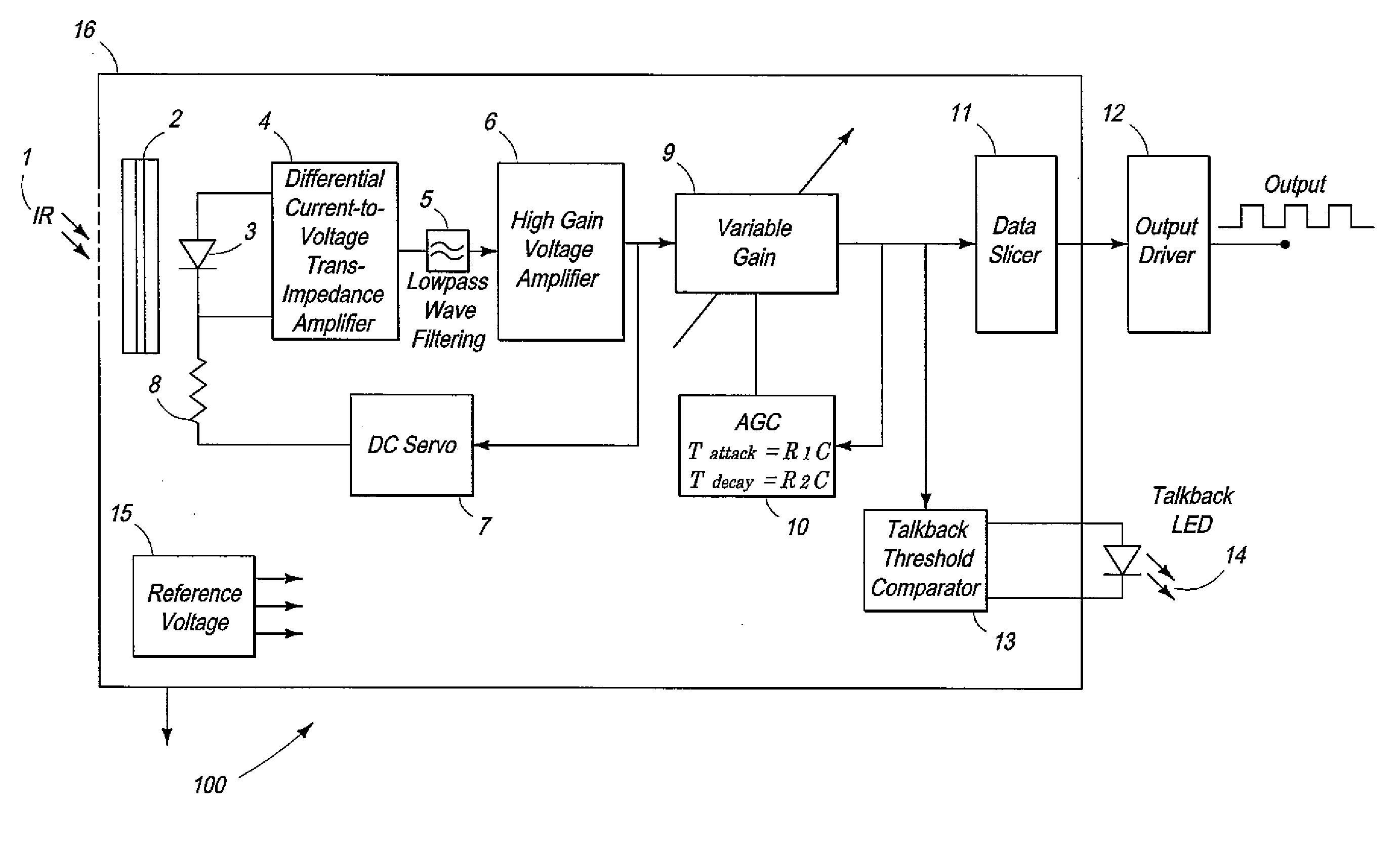
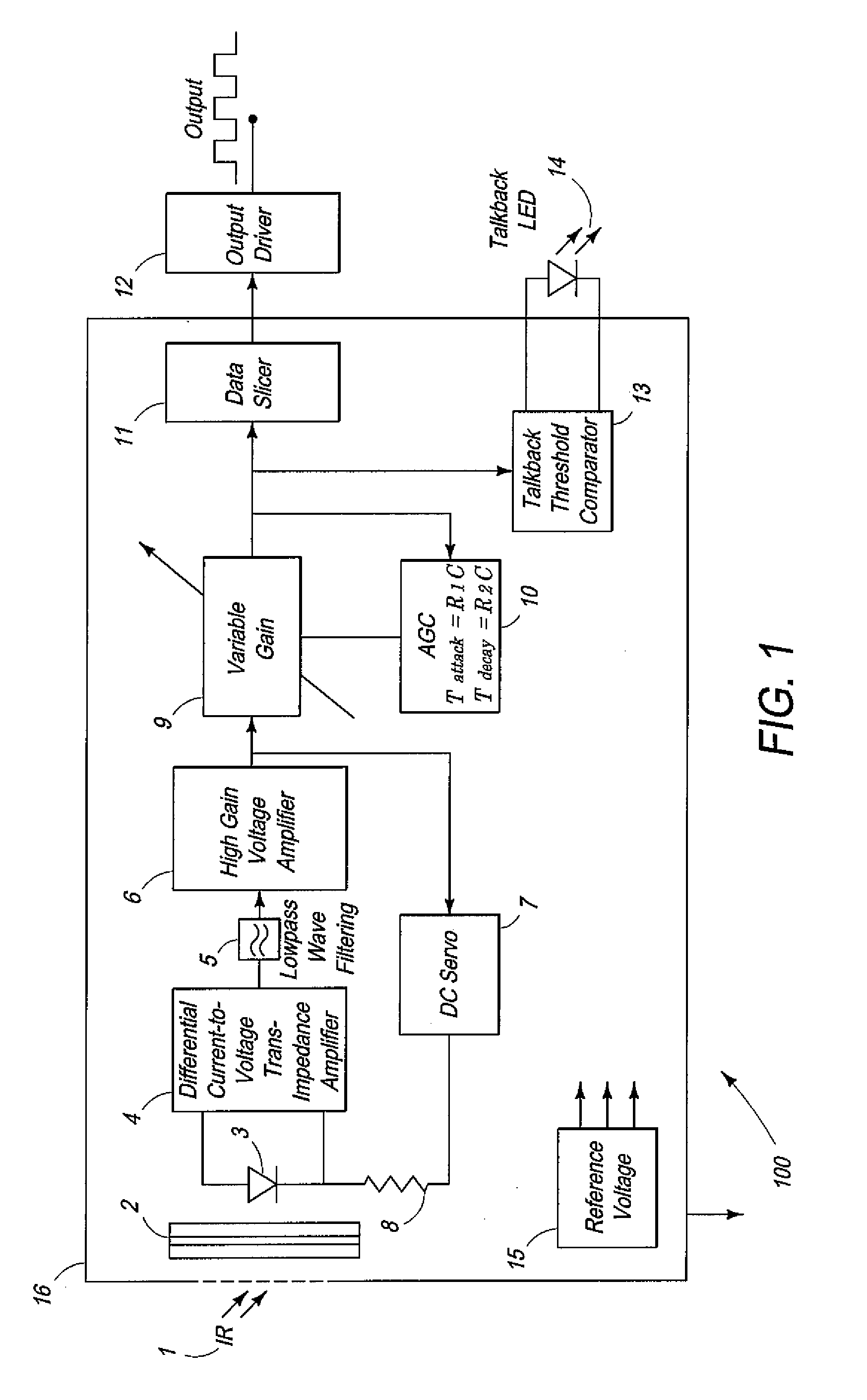
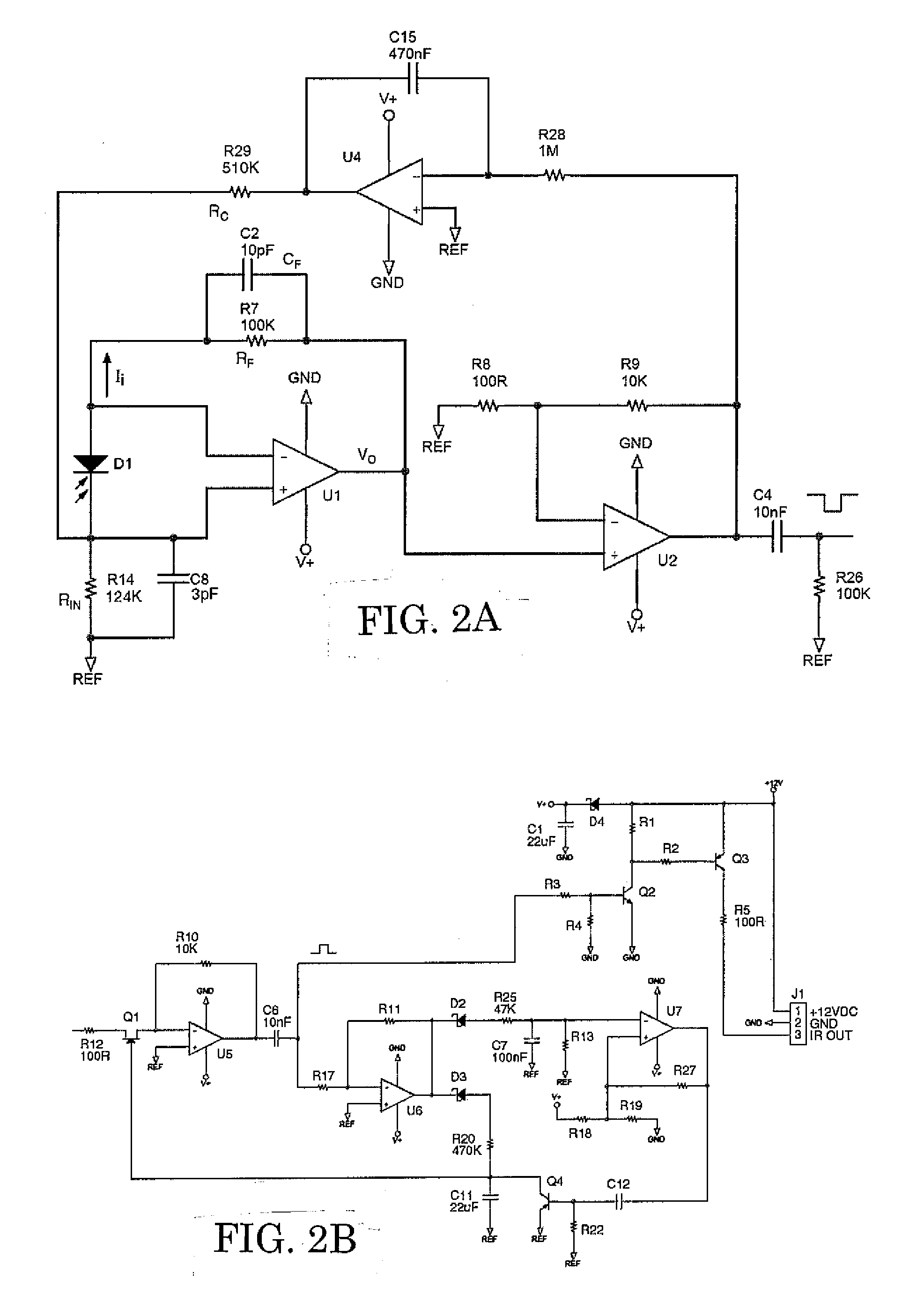
[0026]The present invention overcome these drawbacks and reduces a DC offset error from a first amplification stage to a second amplification stage through a DC servo circuit. The present invention minimizes the output voltage offset from the second stage, thus providing DC coupling that eliminates one, or more interstage coupling capacitors and maintains a normal DC operating point. The invention provides improved low frequency response without increasing capacitive values, with consequent increased settling times through increased DC coupling. The multiplication of DC offset from one high-gain amplifier stage to another is mitigated through the DC servo circuit provided in a feedback loop. The DC coupling allows the original infrared signal to be amplified and re-transmitted accurately despite background noise including DC infrared interference such as from sunlight.

Problems solved by technology

Infrared remote controls are typically limited to line-of-sight applications.
However, increased bit rate comes at the cost of symbol size.
Therefore, the transmitted symbols are less distinct and become exponentially more prone to noise-induced errors due to a reduced time interval between symbols (guard interval).
In other words, noise susceptibility, where one symbol is mistaken for another, increases when more symbols are packed into the same time interval.
Techniques used to increase the guard interval for radio-frequency communication systems cannot be cost-effectively implemented for infrared communication systems.
However, a carrier generator for QAM must have low phase noise and has no practical, low cost solution for the very high frequencies (approximately 300,000 GHz) of infrared communication.
However, as the symbol length increases, the time difference between adjacent symbols decreases, thereby increasing susceptibility to noise and crosstalk.
However, regardless of format, infrared remote control signals all consist of a succession of carrier bursts and gaps.
However, this relatively short mark time presents a significant challenge to infrared repeater systems.
These relatively tight tolerances are not met by conventional infrared repeater systems.
Simply put, the timing fidelity of an infrared repeater system of a high density code is a challenging problem.
Conventional repeaters operate under conditions of a conventional 20-40 cycle burst length and are not designed to handle signals with short burst lengths such as 6 cycles.
Conventional infrared sensors also create distortion in a signal and provide a limited low frequency response resulting in a baseline shift and droop of an amplified infrared signal caused by the unipolar nature of the received infrared signal and capacitive interstage coupling.
The cause of this pulse is low frequency ringing due to inadequate low frequency response in the infrared sensor.
However, baseline shift is an acute problem with high-density codes where the carrier bursts are only a few pulses long.
For example, the RC-MM code uses carrier bursts six pulses long such that an extra pulse will cause significant distortion.
Baseline shift / droop errors in high density codes can range from occasional decoding errors to a complete inability to decode an infrared signal.
Furthermore, if the decoder utilizes envelope detection rather than pulse counting, then the detected pulse will be longer than intended, and will consequently shrink the inter-burst gap that must be preserved if the signal is to be correctly processed.
Conventional infrared repeaters provide an adequate single-pole (−6 dB / octave) high frequency response of approximately 100 kHz, but usually have a low frequency response that rolls off at too high a frequency, typically around 20 kHz (which causes the baseline shift, due to the unipolar nature of infrared signals, to have excessive droop), and at an excessive rate (−6 dB / octave per capacitor), with consequent excessive low frequency phase shift, due to the use of too many inter-stage coupling capacitors (typically 4 or 5).
In low-density infrared formats where there may be twenty carrier cycles per mark, the presence of one or two extra pulses will not usually present a problem significant enough to cause an error.
However, in high-density formats of six cycles per mark, one extra pulse will provide a proportionally much more significant distortion and a high likelihood of errors.
The drawback to this method is the increase in settling times which slow the adaptability of the sensor to changes in the infrared interference background.
Therefore, using larger inter-stage coupling capacitors to remove baseline droop and ringing solves one problem but creates the more serious problem of increased settling time.
In addition to the timing problems inherent to a high density code, the infrared signals are distorted by the environment which it travels through and increase the difficulty in maintaining mark / space timing tolerances.
Electrical noise is also generated internally in repeater components such as the sensor.
However, these strategies do not allow for efficient error correction, and require the infrared sensor to be redesigned for a particular environmental interference parameter.
Another approach of an infrared repeater that fully decodes an infrared signal before re-transmission suffers from latency issues and the inability to handle unknown codes.

Method used


Image

  • Infrared Repeater System
  • Infrared Repeater System
  • Infrared Repeater System

Examples


Embodiment Construction

[0042]One embodiment of an infrared repeater device according to the present invention includes an infrared sensor 100 and at least one infrared flasher (not shown). Flashers may be attached directly over an infrared sensor window as commonly provided on televisions, audio-video receivers or amplifiers. An infrared light-tight blocker boot may optionally be used to prevent devices from responding to infrared signals other than the infrared flasher signal. Along with infrared routing, individual control of a plurality of devices sharing the same infrared codes is provided. Furthermore, a plurality of devices can also be controlled simultaneously.

[0043]An infrared repeater ideally receives and transmits an infrared signal without adding or subtracting from the original signal. However, environmental noise such as wideband infrared interference from televisions, CFLs, sunlight, etc., as well as electrical noise from light dimmers, switching power supplies, etc. will alter the received ...


PUM


Abstract

An infrared sensor includes a photodiode receiving an infrared signal. A first amplifier is connected to the photodiode. A second amplifier is connected to the first amplifier. A DC servo is connected in a feedback loop between the output of the second amplifier and the positive side of the first amplifier. An analog-to-digital signal converter is connected to the second amplifier. An output driver is connected to the analog-to-digital signal converter. The infrared sensor may receive and retransmit an infrared signal and may be incorporated in an infrared repeater system.

Description

BACKGROUND OF THE INVENTION[0001]1. Field of the Invention[0002]This invention relates to an infrared sensor, infrared repeater system, and method of processing an infrared signal.[0003]2. Description of Related Art[0004]Infrared control signals are commonly used in remote control devices to control hardware from a distance. Pulse-code modulation is a known method of electrically controlling infrared light emission from an array of one or more infrared light emitting diodes (LED) housed within a remote control. Such diodes typically emit infrared light in a relatively narrow band in the range of 600-1000 nm, with 940 nm and 950 nm being the most common wavelengths for consumer electronic infrared remote controls.[0005]Infrared remote controls are typically limited to line-of-sight applications. To solve this problem, infrared repeater units, also referred to as infrared extenders, are provided to receive, amplify, and process infrared signals emitted by an infrared remote control fo...

Claims


Application Information

Patent Timeline
IPC IPC(8): G01J5/02G01J5/00
CPCG08C2201/40G08C23/04
Inventor ROXBURGH, ALASTAIRLENSER, RICHARDCAWLFIELD, BILL
Owner CORE BRANDS
Learn More