Ops-laser pumped fiber-laser

a technology of fiber-laser and fiber-amplifiers, which is applied in the direction of laser optical resonator construction, laser details, basic electric elements, etc., can solve the problems of reducing efficiency, reducing absorption efficiency, and excessive heating, and achieves short pump-radiation absorption length, small cladding diameter, and low brightness

Inactive Publication Date: 2010-10-14
COHERENT INC
View PDF11 Cites 10 Cited by
  • Summary
  • Abstract
  • Description
  • Claims
  • Application Information

AI Technical Summary

Benefits of technology

[0015]In another aspect of the present invention the diode-laser bars can be high fill-factor diode-laser bars which have low brightness, but are relatively inexpensive. Only a simple single-element optic is required to concentrate the diode-laser radiation onto a gain structure of the OPS-laser. The OPS-laser converts this low-brightness pump-radiation from the diode-laser bar into single-mode, very high brightness pump-radiation for the gain-fiber.
[0016]The high brightness of the OPS-laser pump-radiation enables pumping double-clad gain-fibers having a relatively small cladding diameter compared with that of gain-fibers that are pumped directly with diode-laser radiation. This is very important for achieving average output power greater than 1 kW, or peak power greater than 10 kW, in a single mode fiber-laser.
[0017]Small cladding diameter provides that that the cladding-to-core area ratio in the gain-fiber cam be correspondingly reduced. This advantageously leads to short pump-radiation absorption length, thus mitigating above discussed nonlinear effects that set the limit to the average and peak power of a prior-art single mode fiber-laser. Fibers having a relatively small core-diameter, for example about 15 μm diameter, and made of phosphor-silicate glass can be used instead commonly used alumino-silicate fibers having a 25 μm core-diameter. Phosphor-silicate fibers are more resistant to “photo-darkening” which typically limits the lifetime of fiber-lasers. Additionally, the small clad-core area ratio provides that that ytterbium (Yb) doped fibers can be pumped “resonantly”, that is at a wavelength that is close to the generated wavelength. An example could be pumping in a 990 nanometers (nm) to 1020 nm wavelength band while emitting at a wavelength between about 1060 and 1090 nm. Low absorption relative to absorption at 915 nm or 976 nm radiation bands in Yb doped cores makes pumping essentially impossible with lower brightness pump beams. This is due to increased length required due to increased length of fibers and onset of above discussed nonlinear effects.
[0018]Resonant pumping minimizes quantum defect and, thus, heat released in the fiber. Such heat release leads to another fundamental limitation of power output possibility in prior-art single mode fiber-lasers. OPS-lasers have sufficient wavelength flexibility to facilitate resonant pumping. Because of the above discussed advantages, the inventive use of diode-pumped OPS-laser radiation for pumping fiber-lasers and fiber-amplifiers can provide fiber-lasers having CW or peak pulse-power levels well in excess of those achievable with prior-art direct diode-laser radiation pumped fiber-lasers to be provided in a cost efficient manner. Other advantages and embodiments of the present invention will be evident to those skilled in the art from the detailed of the present invention provided hereinbelow.

Problems solved by technology

In practice there are limits due, inter alia, to non-linear effects which can broaden the spectrum of pump radiation resulting in reduction of absorption efficiency, and photo-darkening of the fiber material which can lead to reduction of efficiency, excessive heating, and even catastrophic failure.
The non-linear effects become increasingly problematical as the gain-fiber is longer.
In both of the above described approaches optical pumping is limited by limitations of coupling the output of a plurality of diode-laser emitters into an optical fiber.
A problem, however, as far as brightness is concerned, is that the higher the fill-factor of a diode-laser bar the less bright the aggregate output of the bar will be.
Most of these involve complicated combinations of prisms, lenses or polarization sensitive devices, and are relatively expensive and space consuming compared with a simple optical arrangement of a fast-axis collimating lens and a focusing lens that can be used to focus the output of a single emitter.
This expense difference becomes increasingly burdensome when a plurality of such arrangements is required.

Method used


Image

  • Ops-laser pumped fiber-laser
  • Ops-laser pumped fiber-laser
  • Ops-laser pumped fiber-laser

Examples


Embodiment Construction

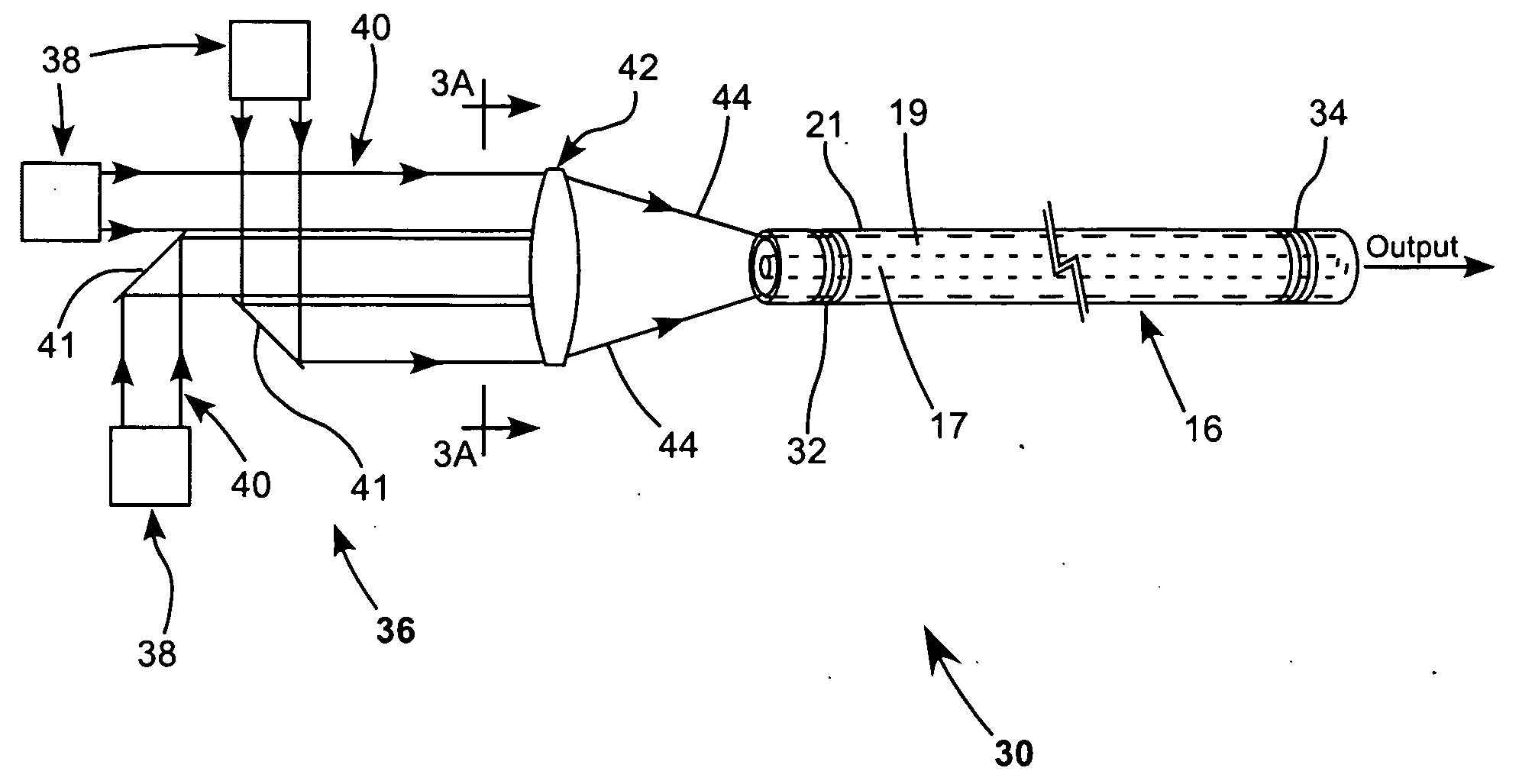
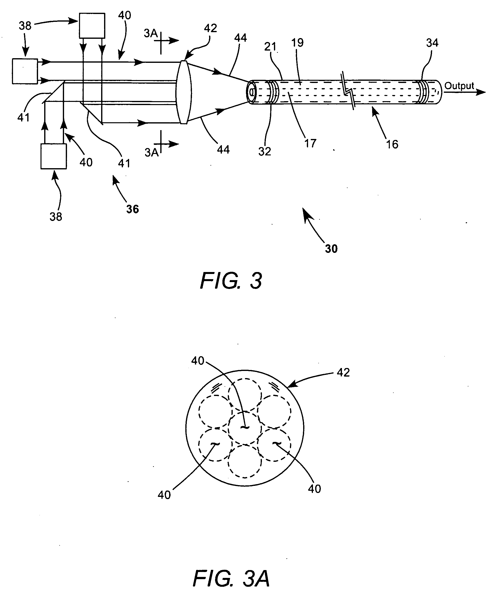
[0034]Referring again to the drawings, wherein like components are designated by like reference numerals, FIG. 3 and FIG. 3A schematically illustrate one preferred embodiment 30 of an OPS-laser pumped fiber-laser in accordance with the present invention. Laser 30 includes a “double-clad” optical gain-fiber 16 having a doped core 17 surrounded by an inner core 19 which is surrounded by an outer core 21. A laser resonator is formed in the gain-fiber between fiber Bragg gratings (FBGs) 32 and 34.

[0035]Optical pump radiation is provided by a pump module 36 including plurality of external-cavity, surface-emitting, semiconductor lasers (OPS-lasers) 38. Each laser delivers a beam of radiation 40 preferably in a single lateral mode or at least a “low-M2” (for example M241, to a positive lens 42. Radiation from all of the beams is focused by lens 42, as indicated by converging rays 40, into inner cladding 19 of gain-fiber 16, with a small portion, of course, directed into core 17. The beams ...


PUM


Abstract

An optical gain-fiber of a fiber-laser or a fiber-amplifier is optically pumped by radiation from a plurality of external cavity, optically pumped, surface-emitting semiconductor lasers (OPS-lasers). In one example, radiation from the OPS-lasers is focused by a lens into cladding of the gain-fiber at one end of the fiber. In another example radiation from the diode-lasers is focused into the core of a delivery fiber at one end of the delivery fiber. The other end of the delivery fiber is coupled to the cladding of the gain-fiber.

Description

TECHNICAL FIELD OF THE INVENTION[0001]The present invention relates in general to fiber-lasers and fiber-amplifiers. The invention relates in particular optically pumping fiber-lasers and fiber-amplifiers with radiation from an array of diode-lasers.DISCUSSION OF BACKGROUND ART[0002]Fiber-lasers, including fiber oscillator / amplifier combinations (MOPAs) are gradually replacing conventional solid-state lasers in several laser applications. Fiber-lasers and amplifiers have advantages over solid-state lasers in ruggedness and optical efficiency. CW fiber-lasers having a very simple architecture are capable of delivering a very high-powered beam, for example, a beam having a power in excess of 1 kilowatt (kW), in a single mode. Pulsed fiber-lasers can deliver peak-power as high as 10 kW or greater. Fiber-lasers can have an optical efficiency, for example between about 60% and 90%.[0003]High-power CW fiber-lasers are extremely useful in material processing applications, such as cutting o...

Claims


Application Information

Patent Timeline
Patent Type & Authority Applications(United States)
IPC IPC(8): H01S3/30
CPCH01S3/067H01S3/094007H01S3/094011H01S3/094057H01S5/183H01S3/09415H01S5/024H01S5/041H01S5/14H01S3/09408
Inventor SPINELLI, LUIS A.GOVORKOV, SERGEI V.CAPRARA, ANDREA
Owner COHERENT INC
Why Eureka
Try Eureka