Ship Flue Gas Scrubbing Equipment And Method

Inactive Publication Date: 2010-10-21
PENG SIGAN
View PDF25 Cites 37 Cited by
  • Summary
  • Abstract
  • Description
  • Claims
  • Application Information

AI Technical Summary

Benefits of technology

[0021]Embodiments of the present invention also intend to overcome the shortcomings of existing ship flue gas scrubbing method. The present application provides a ship flue gas scrubbing method which first cools the high temperature exhaust gas and then passes the gas through fillings to scrub. It separates the cooling and scrubbing into two steps to achiev

Problems solved by technology

Currently available technologies have certain unsolved problems on economic and efficiency, some of which are discussed below.
Firstly, the technology uses a hollow fiber contactor as scrubber. This hollow fiber contactor only tolerates tens of centigrade. It can not be used for high-temperature gas, especially for the ship engine exhaust with temperature as high as 200-490° C.
Secondly, pressure drop and resistance are very high when the hollow fiber contactor is used for scrubbing. Operation cost and energy expenditure would be quite high if additional booster fan is installed.
The higher the temperature, the worse is the scrubbing effect.
Firstly, it is difficult to overcome the conflict between scrubbing effect and operational cost.
The bubbling scrubbing technology is minimally efficient in gas-liquid transfer.
However, the mentioned is limited by available space on the ship for exhaust gas scrubbing, and it employs a single large bubbling hood.
This causes a low transfer efficiency.
Pressure loss of the bubbling scrubbing operation method is the energy loss by the exhaust to overcome the liquid pressure.
The scrubbing performs better as the pressure loss increases, but the running cost also rises.
This indicates the conflict of scrubbing effect and running cost that is hard to solve.
With such a shallow immerse, the overall gas-liquid contact surface is still extremely limited even if the ‘mixed vanes’ is added to form turbulence in the exhaust gases, forming highly dispersed tiny bubbles.
As a result, the scrubbing and absorbing efficiency is very low.
In order to reach better scrubbing performance, the exhaust immerse depth and pressure loss must increase, hence the energy consumption and running cost

Method used


Image

  • Ship Flue Gas Scrubbing Equipment And Method
  • Ship Flue Gas Scrubbing Equipment And Method
  • Ship Flue Gas Scrubbing Equipment And Method

Examples


application examples

[0065]Further description for the ship flue gas scrubbing equipment and method are given below combining figures and examples.

A. Examples for the Ship Flue Gas Scrubbing Equipment

example 1

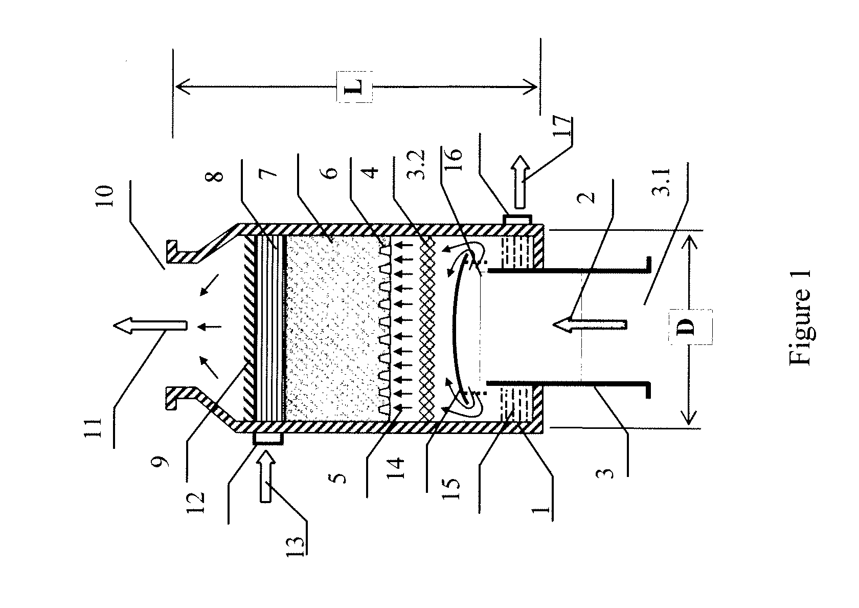
[0066]As depicted in FIG. 1, an application in which the gas lead-in port 3.2 is fixed at the bottom portion of the shell 1 and reaches to the exit of the smoke pipe 3 inside the shell 1. It maintains the smoke pipe 3 staying above acidic seawater surface of the water tank 15, that is, the exhaust gas does not enter the acid seawater. It is suitable for situations where the flue gas is lead in vertically. It comprises a shell 1, a scrubbing section 7 which contains fillings. A water tank 15 with a seawater outlet 16 lies in the lower portion of the shell. On the wall of the said shell 1, there exists a smoke pipe 3 which lead the to-be-scrubbed exhaust gas into the shell 1 from the outside. One end of the smoke pipe 3 is the gas inlet 3.1, the other end is the gas lead-in port 3.2; the gas lead-in port 3.2 extends into the shell 1, and it lies between the scrubbing section 7 and water tank 15; the cooler 4 which used for cooling the high temperature gas 2 lies on the gas passage tha...

example 2

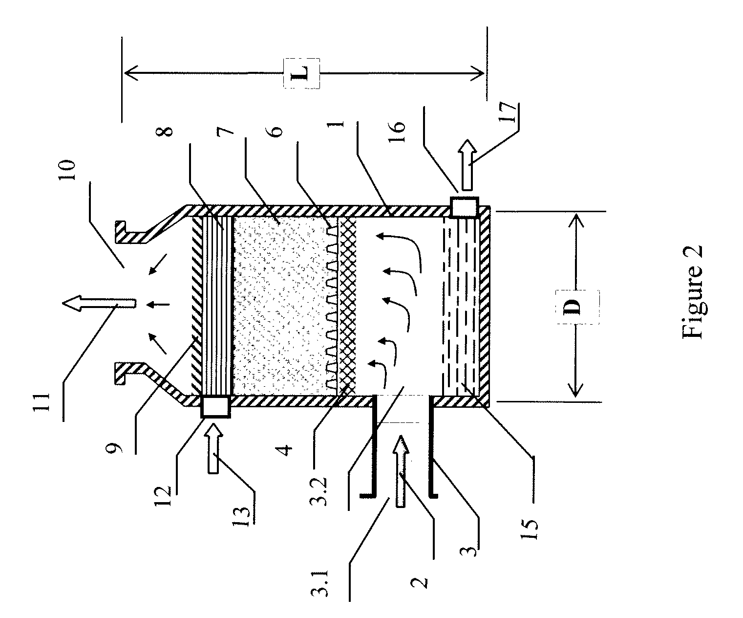
[0078]Depicted in FIG. 2 is another application for this ship flue gas scrubbing equipment. The difference to Example 1 is that the gas lead-in port 3.2 inside the shell 1 is at the shell 1, and it is an exit of the smoke pipe 3 that fixed on the wall of the shell 1. It maintains the smoke pipe 3 staying above acidic seawater surface of the water tank 15, that is, the exhaust gas does not enter the acid seawater. It is suitable for situations where the flue gas enters the scrubber horizontally and then goes upside. The water tank 15 comprises of wall and bottom portion of the shell 1 which below the horizontal cross-section of the inside-shell gas lead-in port 3.2 lower edge.


PUM

PropertyMeasurementUnit
Lengthaaaaaaaaaa
Temperatureaaaaaaaaaa
Pressureaaaaaaaaaa

Abstract

This invention involves a marine ship flue gas scrubbing equipment and scrubbing method. The equipment includes a shell with an upper scrubbing section and a water tank in the lower section. A smoke pipe leads in exhaust gas to an area between the scrubbing section and water tank. Scrubbing seawater is injected through an inlet above the scrubbing section, and a cooler is located along the pathway of the exhaust gas. The method of scrubbing includes leading-in exhaust gas, cooling the exhaust gas, injecting scrubbing seawater, performing scrubbing operation, and discharging clean gas. Embodiments of the invention provide a highly efficient scrubbing equipment and method suitable for high-temperature exhaust gas within a limited usable space. The methods and equipment are highly effective for emission reduction, has low energy consumption, small size, and long life performance.

Description

FIELD OF THE INVENTION[0001]This invention involves a marine ship flue gas scrubbing equipment and scrubbing method. It employs seawater to scrub and reduce sulfur dioxide and other pollutants discharged by marine ships. It belongs to the field of environmental protection, and more specifically, to the field of ships' exhaust pollutant prevention and control.DESCRIPTION OF RELATED ART[0002]In the past 20 years, international legislation about air pollutant reduction, mainly the sulfur dioxide pollutant reduction, is getting stricter and more mature. In recent years the restriction target ranges from land-based facilities to marine ships.[0003]After the sulfur dioxide reduction issue was brought out world widely, the trend that value the seawater flue gas desulphurization (FGD) technology appeared soon. In 2007, a scholarly research publication from the Alliance for Global Sustainability (involving four universities: Massachusetts Institute of Technology, University of Tokyo, Chalmer...

Claims


Application Information

Patent Timeline
IPC IPC(8): B01D53/50F01N3/10
CPCB01D53/1481B01D53/18B01D53/78B01D2258/012B01D53/507B01D2252/1035B01D2257/302B01D2259/4566B01D47/02B01D47/14
Inventor PENG, SIGAN
Owner PENG SIGAN
Why Eureka
Try Eureka