

Positive Electrode Mixture for Nonaqueous Battery and Positive Electrode Structure
- Summary
- Abstract
- Description
- Claims
- Application Information
AI Technical Summary
Benefits of technology
Problems solved by technology
Method used
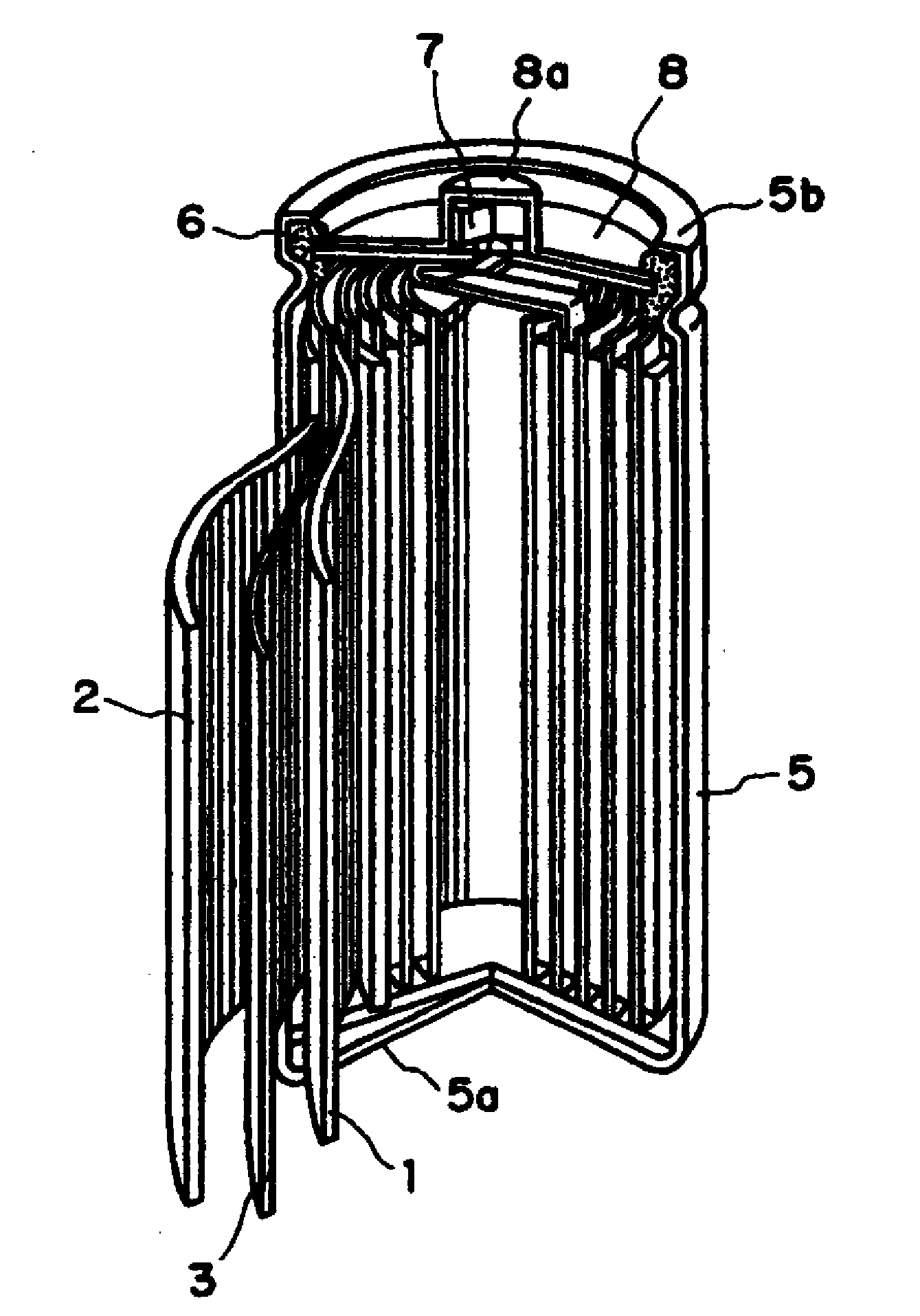
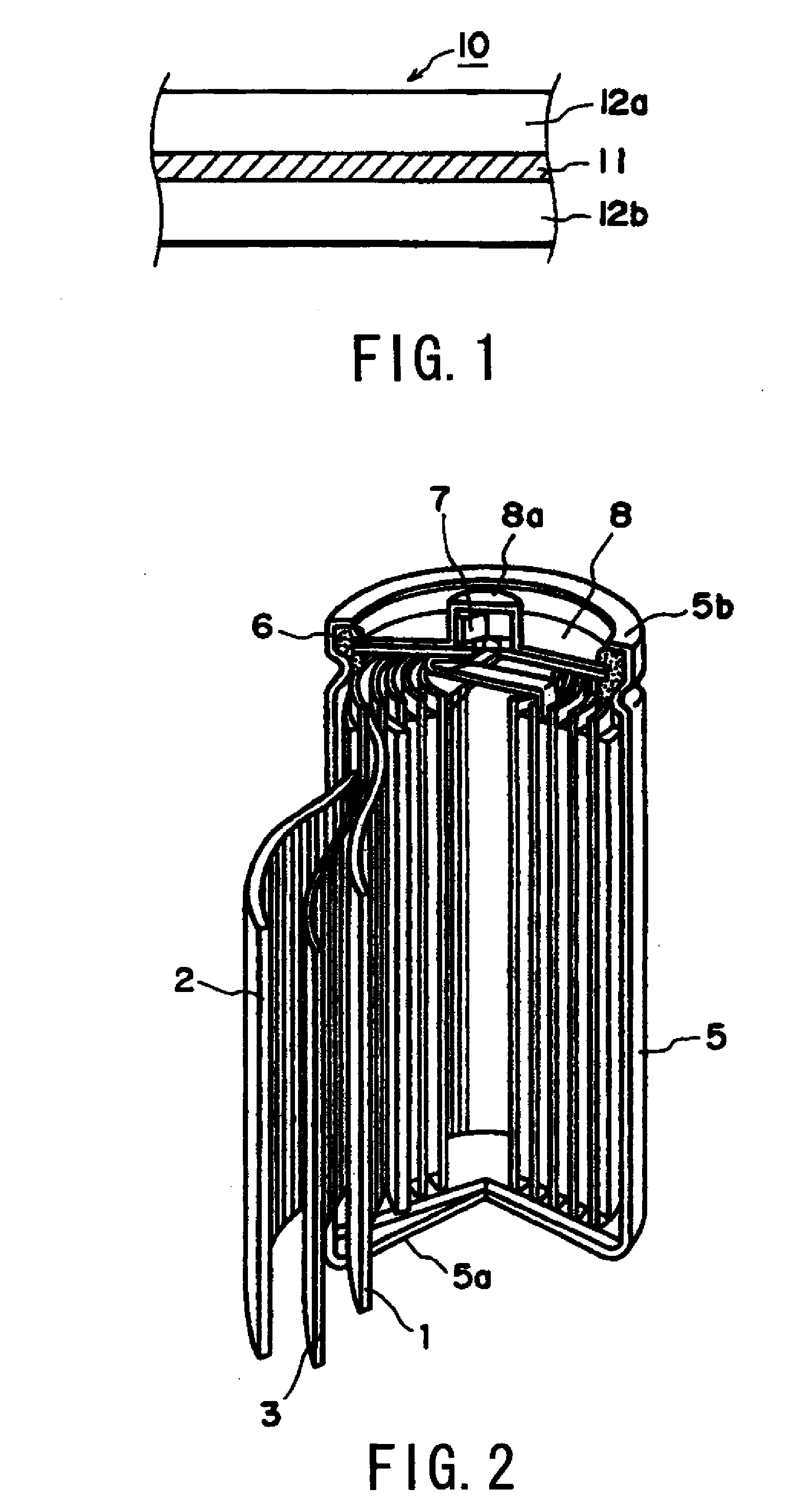
Image

Examples
example 1
[0049]LiCoO2: 100 wt. parts, Electroconductive-additive A: 1 wt. part, Polymer A: 3 wt. parts, oxalic acid (organic acid): 0.005 wt. part (0.5 wt. part per 100 wt. parts of electroconductive-additive), and NMP (N-methyl-pyrrolidone) were mixed, and kneaded for 5 minutes by using a kneading machine (“AR-250” made by THINKY Corporation) to prepare an electrode mixture slurry having an adjusted solid matter concentration ((LiCoO2+electroconductive-additive+polymer) / slurry weight).
[0050]The above slurry was applied onto one side of 20 μm-thick aluminum foil by using a coating roller-type coater (“TOSMAC100 WI-E” by Toyo System Co. Ltd.), and dried at a line speed of 0.3 m / min. (in a drying furnace having a line length of 1 m) under the conditions of 130° C. and a wind velocity setting of 50%. The thus-obtained electrode exhibited a coating rate (=positive-electrode-mixture layer solid content weight per unit area) of 473 g / m2 and a coating film (positive-electrode-mixture layer) thickne...
examples 2-8
[0052]Electrode mixture slurries and electrodes were obtained in the same manner as in Example 1 except for replacing the oxalic acid as an organic acid with oxalic acid or maleic acid in amounts of 0.012 to 0.10 wt. parts (1.2 to 10 wt. parts per 100 wt. parts of electroconductive additive), as shown in Table 1.
example 9
[0053]An electrode mixture slurry and an electrode were obtained in the same manner as in Example 1 except for using Electroconductive additive B (“Printex XE2” made by Degussa) as an electroconductive additive instead of Electroconductive additive A (Ketjen Black) and using maleic acid 0.03 wt. part instead of the oxalic acid.
PUM
 Abstract
Description
Claims
Application Information