Electromagnetic - acoustic converter

a technology of electromagnetic and acoustic converter, applied in the direction of analyzing solids using sonic/ultrasonic/infrasonic waves, blast furnace components, blast furnaces, etc., can solve the problem of interference for receiving useful signals from objects, restricted case size, and high level of acoustic interference, so as to increase the operational durability of emat and the effect of high resistance properties

Inactive Publication Date: 2010-10-28
KIRIKOV ANDREY VASILIEVICH +3
View PDF8 Cites 2 Cited by
  • Summary
  • Abstract
  • Description
  • Claims
  • Application Information

AI Technical Summary

Benefits of technology

[0024]The ceramic protector of the electromagnetic acoustic transducer according to the present invention is an element jointly forming the air cushion and determining operational durability of EMAT. Homogeneity of the material present in zone of aggressive effect of the object under test, high resistance properties of ceramics in relation to friction, deterioration, mechanical damages, erosion, temperature effect, render a strongly pronounced positive role in increasing of operational durability of EMAT.

Problems solved by technology

Diminution of the case size, however, is restricted by size of the inductor or group of inductors.
Deficiency of such EMAT is in rather high level of acoustic interferences caused by occurrences of acoustic stray coupling between inductors and protector and small size of the protector.
Due to occurrence in practice of inevitable acoustic coupling between the inductor and the protector, elastic vibrations are generated in the latter propagating to closely situated borders of the protector, reflected then from these borders and coming back in the inductor zone, generating electrical pulses therein which can make interference for reception of useful signals from the object under test.
Deficiency of such EMAT is also their rather low interference protection caused by occurrences of stray electromagnetic coupling between metal details of the transducer (substrate) and the inspected object.
Considerable amplitude and a wide frequency spectrum of the interference caused by these phenomena can lead to essential decrease in sensitivity and reliability of the ultrasonic inspection.
High probability of interference generation occurs not only at immediate contact of the metal substrate and the inspected item, but also at small clearance therebetween that is caused by capacitive coupling “substrate-metal under test”.
A source of interference can also be created by currents induced by sounding pulse in the shield of cable connecting the transducer with electronic systems, and also the inductor on the surface of the inspected item.
Other deficiency of the EMAT having a protector with size and shape corresponding to the inductor or group of inductors is low mechanical, temperature and erosive durability of such construction.
At the same time, the metal under test may have unevennesses, protruding defects on the surface and deviations of shape from the nominal.
Besides, the solid particles of calx torn off by compressed air flow forming the air cushion, being accelerated to high speed, render erosive, destroying effect to the transducer working surface.
Scores, grazes local attritions sharply reduce efficiency of the air cushion.
The adhesive joint between the ceramics periphery and the substrate is subject to especially intensive erosion.
In course of high-temperature ultrasonic inspection the “heating-cooling” cycles also negatively influence service life of the EMAT because of difference in expansion factors of used materials.

Method used


Image

  • Electromagnetic - acoustic converter
  • Electromagnetic - acoustic converter

Examples


Embodiment Construction

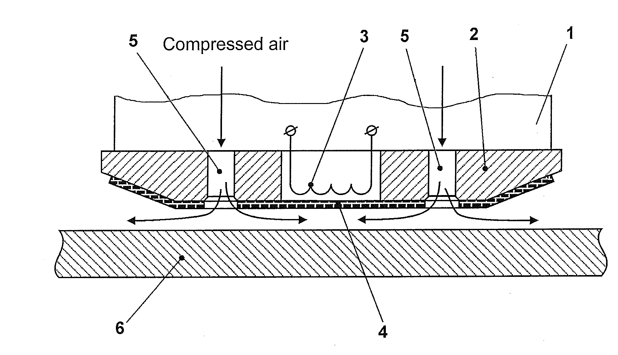
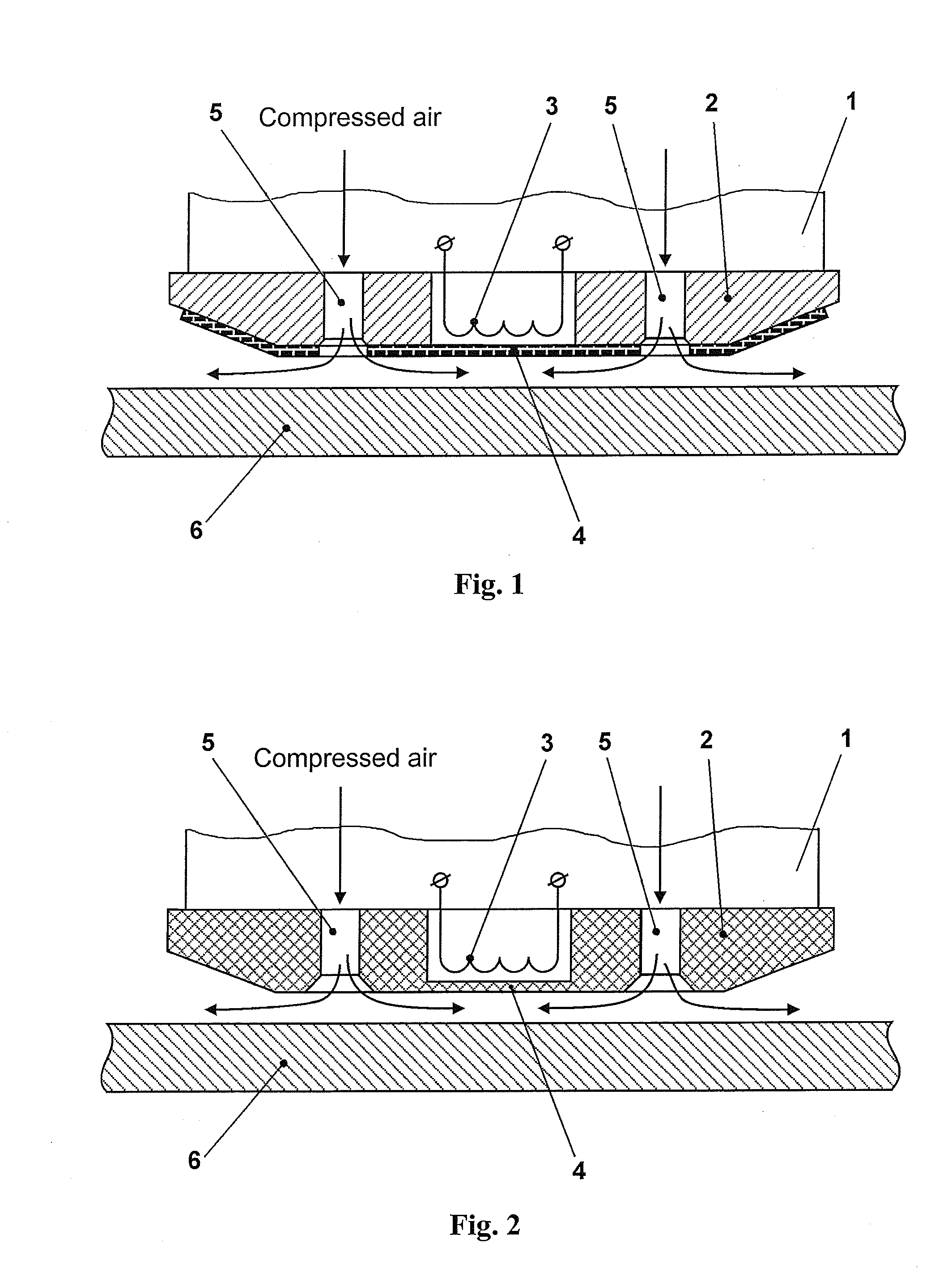
[0027]Shown in FIG. 1 electromagnetic acoustic transducer (EMAT) includes case 1 (illustrated symbolically) fixed thereto from the side faced to the inspected object 6 substrate 2 with holes 5 for air supply, inductor 3 provided in the substrate and ceramic protector 4. Other elements of EMAT, such as concentrator, magnetic circuit, connecting cable are conventionally not shown.

[0028]The substrate 2 is made from aluminium or aluminium alloy, and the ceramic protector 4 is formed in form of a ceramic plate of preferentially constant thickness. The ceramic plate forming protector 4 is made of such size that its periphery embraces holes 5 in substrate 2. Preferably the area of a ceramic plate substantially is equal to area of the lower face of substrate 2, and the shape of the ceramic plate substantially coincides with the shape of the lower face of substrate 2. The ceramic plate is rigidly fixed to the lower face of substrate 2, e.g. adhered thereto. Holes are foamed in the ceramic pl...


PUM

PropertyMeasurementUnit
thicknessaaaaaaaaaa
sizesaaaaaaaaaa
shapeaaaaaaaaaa

Abstract

An electromagnetic acoustic transducer (EMAT) relates to the field of nondestructive, in particular, ultrasonic inspection of materials and items and can be used for testing of rolled sheet and section steel, and also pipes. The EMAT comprises a case with a substrate, at least one inductor and a protector covering the inductor from the substrate backside in form of a ceramic plate, holes are formed in the substrate for air supply generating in course of operation an air cushion between the lower face of substrate and the object under test. According to the invention the ceramic plate is provided on the lower face of the substrate and has such size, that its exterior outline embraces the holes in the substrate, thus holes are formed in said plate, said holes are coaxial to holes in the case. Shape of the ceramic plate substantially coincides with the shape of the substrate lower face and its square is substantially equal to square of the lower face of the substrate. In other alternative embodiment of the invention the substrate is made from ceramics and formed integrally with the protector. The invention allows increasing sensitivity, interference protection and reliability of the ultrasonic inspection due to decrease in the acoustic coupling negative influence between the inductor and the protector, diminution of electric and electromagnetic coupling between the transducer and the object under test and decrease in level of electrical and electromagnetic interferences caused by this coupling.

Description

TECHNICAL FIELD [0001]The invention relates to the field of nondestructive, in particular, ultrasonic inspection of materials and items and can be used for testing of rolled sheet and section steel, and also pipes.BACKGROUND ART [0002]It is known an electromagnetic acoustic transducer (EMAT) according to RU 2295125 including an inductor or group of inductors, a case made of nonferromagnetic metal, and also a dielectric, more often, ceramic protector pasted-in the case around the inductors. The known transducer comprises a case, an inductor and a protector in form of a ceramic plate, intended for inductor protection against damages. The protector protects only the inductor from mechanical damages and has, as a rule, rather small sizes comparable to size of the inductor or the group of inductors and a shape corresponding to the inductors.[0003]The working plane of the protector, as a rule, is on the same level with the working surface of the case or is a little recessed in it. It may ...

Claims


Application Information

Patent Timeline
Patent Type & Authority Applications(United States)
IPC IPC(8): G01N29/04
CPCG01N29/2412
Inventor KIRIKOV, ANDREY VASILIEVICHDAN, WALDEMARBRITVIN, VLADIMIR ALEXANDROVICHKASHIN, ALEXEY MIKHAILOVICH
Owner KIRIKOV ANDREY VASILIEVICH
Why Eureka
Try Eureka