
Retort furnace for heat and/or thermochemical treatment

a technology of thermochemical treatment and refractive furnace, which is applied in the direction of furnaces, high-frequency/infra-red heating, baking, etc., can solve the problems of increasing loss, not meeting the +/3° c. requirement, or even less stringent requirements, etc., and achieves the effect of preventing heat loss and low working temperatur

Active Publication Date: 2010-10-28
SECOWARWICK
View PDF10 Cites 3 Cited by
  • Summary
  • Abstract
  • Description
  • Claims
  • Application Information

AI Technical Summary

Benefits of technology

[0004]To allow opening of the furnace and putting the charge in the working space, the retort is equipped with a lid. The lid is sealed against the retort with a flange connection, where both the lid and the retort have flanges, and a rubber o-ring or a lip seal is the sealing element. The sealing flanges of the retort and the lid are water-cooled to ensure sufficiently low working temperature: about 80° C. The lid is closed and sealed with a mechanism that clamps both flanges with the seal in between. The lid also has thermal insulation preventing heat losses.

Problems solved by technology

Factors negatively impacting the parameter include all heat bridges and losses in result of radiation or lack of heating elements.
There are heat bridges and the losses are increased by the water-cooled flanges, gas system ferrules and measurement sensors.
In furnaces designed for vacuum operation, especially high vacuum, the ferrule of the pump system can take up a significant part of the lid surface and can cause very high heat losses that considerably upset the temperature distribution evenness, which makes it impossible to meet the + / −3° C. requirement, or even less stringent requirements.

Method used


Image

  • Retort furnace for heat and/or thermochemical treatment
  • Retort furnace for heat and/or thermochemical treatment

Examples


Embodiment Construction

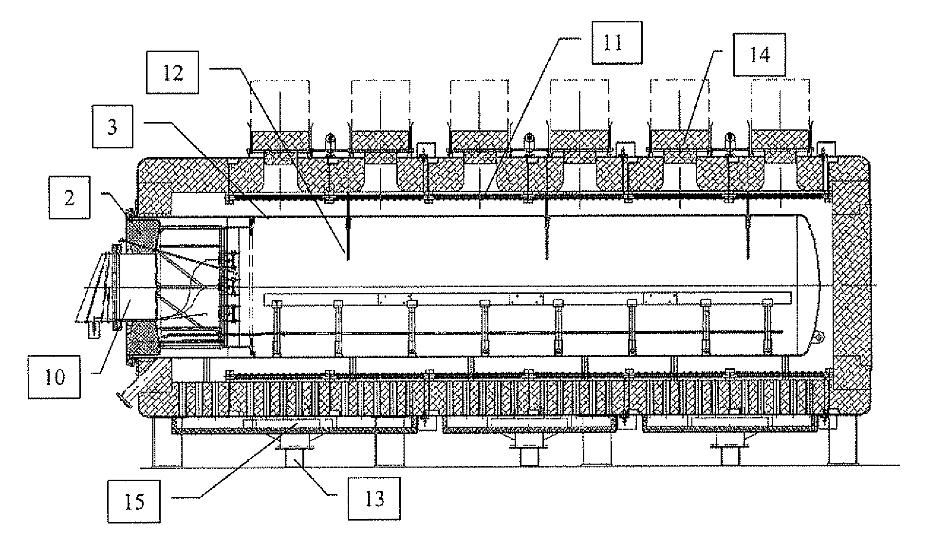
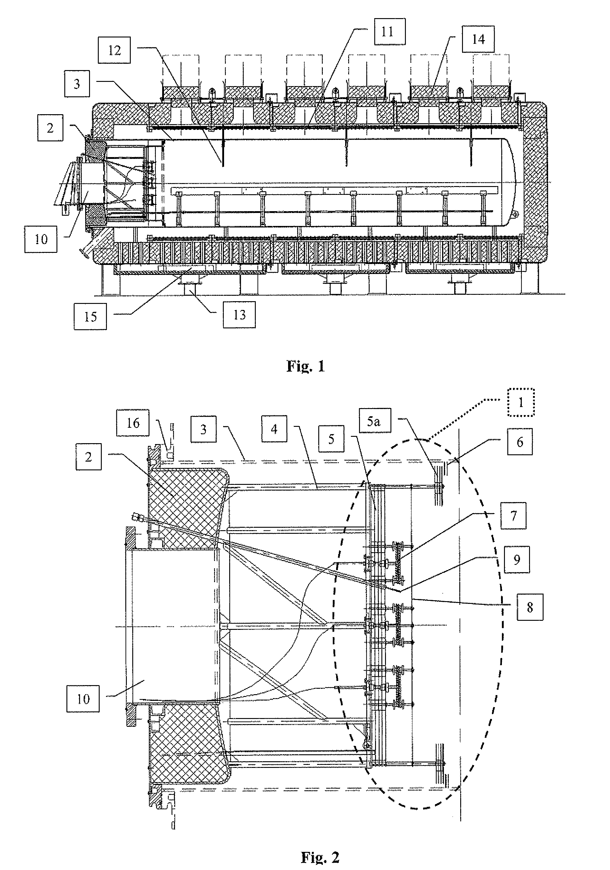
[0031]The invention will be further illustrated in an exemplary, not limiting application, for which FIG. 1 shows a cross-section of the furnace in the vertical plane going through the longitudinal axis of the furnace, and FIG. 2 shows the furnace lid with an insulation system, hereinafter referred to as the thermal barrier, in the horizontal plane going through the longitudinal axis of the lid.

[0032]The thermal barrier 1 (FIG. 2) is made up by brackets 4 located in the lid 2 inside the retort 3, used as support for radiation screens 5, in the form of metal screens with radiation sealing rings 5a, supporting circumferential sealing rings 6, permanently fixed at the inner surface of the retort 3. Additionally, there is a heating system 7 with a temperature evening screen 8 and thermocouple 9, ensuring temperature regulation of the thermal barrier 1 and its active operation. Keeping the temperature of the thermal barrier 1 the same as the temperature in the working space, the heat str...


PUM

PropertyMeasurementUnit
Creep rateaaaaaaaaaa
Electrical resistanceaaaaaaaaaa
Areaaaaaaaaaaa

Abstract

A retort furnace designed for heat and heat and chemical treatment in protective gas atmosphere, process gas atmosphere or in vacuum, equipped with a retort with a lid, made of steel or heat-resisting or creep-resisting alloys, separating the process atmosphere from the ambient atmosphere, with heating elements and thermal insulation outside the retort and with a cooling system. The radiation screens, in the form of at least two metal boards, are installed at supports located at the lid inside the retort; the heating elements are located behind the radiation screens, on the retort side and are separated with the metal screen. A few radiation sealing rings are placed in the extreme area of the brackets. The radiation screens and sealing rings, as well as the circumferential sealing rings permanently fixed in the casing of retort make up the system of reducing heat losses through radiation at the wall of the retort.

Description

[0001]The subject matter of the invention is a retort furnace for heat and / or thermochemical treatment designed for technological processes in protective gas atmosphere, process gas atmosphere or in vacuum.BACKGROUND[0002]Known constructions of retort furnaces have a chamber separating the working space from the ambient environment and ensuring achieving the required purity and quality of the process atmosphere. The retort chamber is made of heat-resisting or creep-resisting alloys and allows working temperatures up to 1300° C. The retorts have outside heat insulation and heating elements in between. The elements provide heat energy that is accumulated using the insulation and is further directed to the retort through radiation and natural convection. Heat is transferred within the retort—from its walls to the charge—in result of radiation, natural convection or convection forced using atmosphere mixers.[0003]Usually the furnaces are equipped with systems for accelerated cooling aft...

Claims


Application Information

Patent Timeline
IPC IPC(8): F27D11/12
CPCC21D1/773F27D1/1858F27B5/06C21D9/0006
Inventor KORECKI, MACIEJLUZENCZYK, ROBERTOLEJNIK, JOZEF
Owner SECOWARWICK
Learn More