
System and method for protection of scr catalyst and control of multiple emissions

a technology of scr catalyst and protection method, which is applied in the direction of physical/chemical process catalyst, separation process, dispersed particle separation, etc., can solve the problems of ammonia level, precious metal catalysts are less attractive, and their potential to oxidize, so as to increase the active life of scr catalys

Active Publication Date: 2010-10-28
THE BABCOCK & WILCOX CO
View PDF18 Cites 18 Cited by
  • Summary
  • Abstract
  • Description
  • Claims
  • Application Information

AI Technical Summary

Benefits of technology

The present invention relates to a method and apparatus for reducing or preventing the poisoning and contamination of an SCR catalyst in combustion devices such as boilers or power plants. The invention involves the use of an iron-bearing compound that reacts with gaseous phosphorus compounds or phosphorus-containing compounds present in the combustion zone or flue gas to form less reactive iron-phosphorus compounds. This helps to increase the active life of the SCR catalyst and sequester phosphorus compounds and mercury, which can be present in the combustion zone or flue gas. The invention provides a new and useful method for protecting the SCR catalyst and controlling emissions in combustion devices.

Problems solved by technology

Rather, it is a practical limit set to prevent excessive levels of ammonia slip.
The major drawback of the base metal catalyst is its potential to oxidize SO2 to SO3; the degree of oxidation varies based on catalyst chemical formulation.
However, SO2 oxidation to SO3 and high material costs often make precious metal catalysts less attractive.
More particularly, as the SCR catalysts are exposed to the dust laden flue gas there are numerous mechanisms including blinding, masking and poisoning that deactivates the catalyst and causes a decrease in the catalyst's performance over time.
While this treatment process does an excellent job of removing the desired poisons it produces wastewater with very high arsenic concentrations.
In another situation, Powder River Basin / Lignite coal plants, any coal / biomass co-combustion, or any coal / bone meal co-combustion or even pure biomass combustion power plants will suffer from phosphorus contamination of their SCR catalysts.

Method used


Image

  • System and method for protection of scr catalyst and control of multiple emissions
  • System and method for protection of scr catalyst and control of multiple emissions

Examples


Embodiment Construction

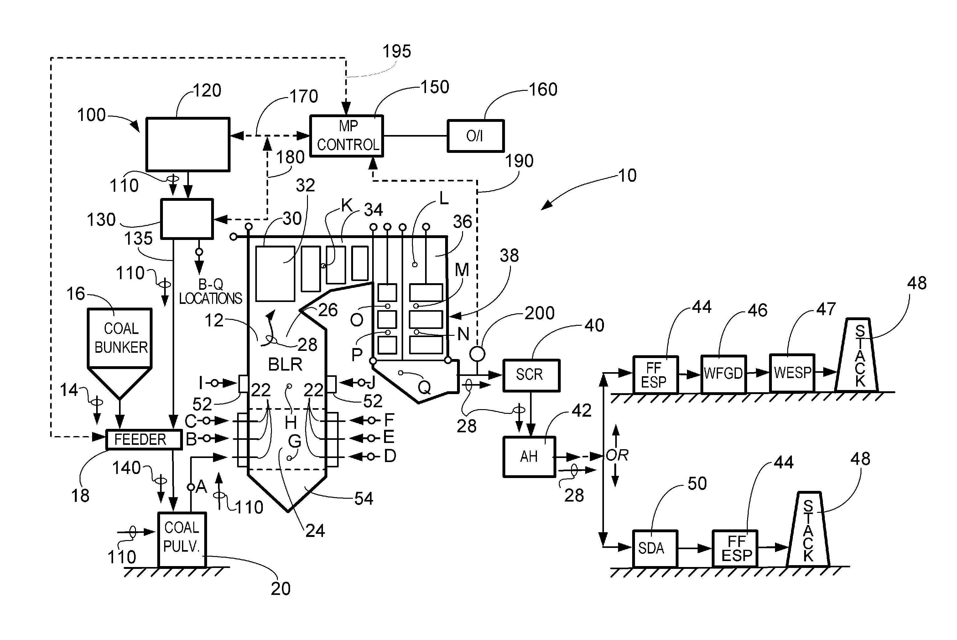
[0027]While the present invention will be described in terms of SCR systems which use ammonia as the NOx reducing agent, since ammonia is frequently preferred for economic reasons, the present invention is not limited to ammonia based systems. The concepts of the present invention can be used in any system which uses an ammoniacal compound. As used in the present disclosure, an ammoniacal compound is a term meant to include compounds such as urea, ammonium sulfate, cyanuric acid, and organic amines as well as ammonia (NH3). These compounds could be used as reducing agents in addition to ammonia, but as mentioned above, ammonia is frequently preferred for economic reasons. Some non-ammoniacal compounds such as carbon monoxide or methane can be used as well, but with loss in effectiveness.

[0028]Although the present invention is described in relation to a boiler, or a fossil fuel boiler, it is not limited solely thereto. Instead, the present invention can be applied to any combustion s...


PUM


Abstract

The present invention relates generally to the field of emission control equipment for boilers, heaters, kilns, or other flue gas-, or combustion gas-, generating devices (e.g., those located at power plants, processing plants, etc.) and, in particular to a new and useful method and apparatus for preventing the poisoning and / or contamination of an SCR catalyst. In another embodiment, the method and apparatus of the present invention is designed to protect an SCR catalyst, while simultaneously providing emission control.

Description

RELATED APPLICATION DATA[0001]This patent application claims priority to U.S. Provisional Patent Application No. 61 / 171,619 filed Apr. 22, 2009 and titled “System and Method for Protection of SCR Catalyst.” The complete text of this application is hereby incorporated by reference as though fully set forth herein in its entirety.FIELD AND BACKGROUND OF THE INVENTION[0002]1. Field of the Invention[0003]The present invention relates generally to the field of emission control equipment for boilers, heaters, kilns, or other flue gas-, or combustion gas-, generating devices (e.g., those located at power plants, processing plants, etc.) and, in particular to a new and useful method and apparatus for reducing or preventing the poisoning and / or contamination of an SCR catalyst. In another embodiment, the method and apparatus of the present invention is designed to protect the SCR catalyst.[0004]2. Description of the Related Art[0005]NOx refers to the cumulative emissions of nitric oxide (NO)...

Claims


Application Information

Patent Timeline
Patent Type & Authority Applications(United States)
IPC IPC(8): B01J27/185
CPCB01D53/8696B01D53/46
Inventor GADGIL, MANDAR R.GHORISHI, S. BEHROOZTONN, DONALD P.
Owner THE BABCOCK & WILCOX CO
Learn More