Balloon catheter and method of manufacture of the same

a technology of balloon catheter and manufacturing method, which is applied in the field of balloon catheter, can solve the problems of difficult withdrawal of balloon, and achieve the effects of easy and precise control, low cost, and high aspect ratio

Inactive Publication Date: 2010-10-28
PRESSURE PROD MEDICAL SUPPLIES INC
View PDF18 Cites 24 Cited by
  • Summary
  • Abstract
  • Description
  • Claims
  • Application Information

AI Technical Summary

Benefits of technology

[0017]A catheter balloon of the illustrated embodiment is characterized by a collar or pillow-shape giving it a high aspect ratio and may be made of any type of material and made by any type of process, although welding processes are preferred. The material may be extensible or nonextensible (compliant / noncompliant). Any material may be theoretically used for the balloon, although urethane and isoprene are preferred. The butt welding of the balloon material to the butt-ends of the inner and outer catheters allows for an unexpected flatness or closeness in wrapping the balloon material around an inner catheter so that the outer diameter of the outer catheter is closely approximated by the outer envelope of the wrapped balloon. Two flat squares of polyurethane are butt solvent-welded to pliable catheters and a hole punch out through the hollow catheter. The butt welding allows a much smaller diameter to be realized of the folded balloon on the catheter than is realizable through lap welding used in the prior art. The two hollow catheters are telescoped together with their squares and then the two squares are a circularly heat welded together. The excess material outside the circular weld is trimmed away. The thickness of the circular heat weld is easily and precisely controllable. The manufacturing method is substantially less costly than the prior art method of blow molding extensible biomedical occlusion balloons. The resulting manufactured balloon can be readily made with a high diameter to length aspect ratio and be attached to small catheters 6 F and below, which was not a prior art capability.

Problems solved by technology

This in turn requires a larger balloon making the balloon more difficult to withdraw into a small diameter delivery catheter (not shown) and is more prone due to the length to occlude branch coronary sinus vessels near the coronary sinus ostium.

Method used


Image

  • Balloon catheter and method of manufacture of the same
  • Balloon catheter and method of manufacture of the same
  • Balloon catheter and method of manufacture of the same

Examples


Embodiment Construction

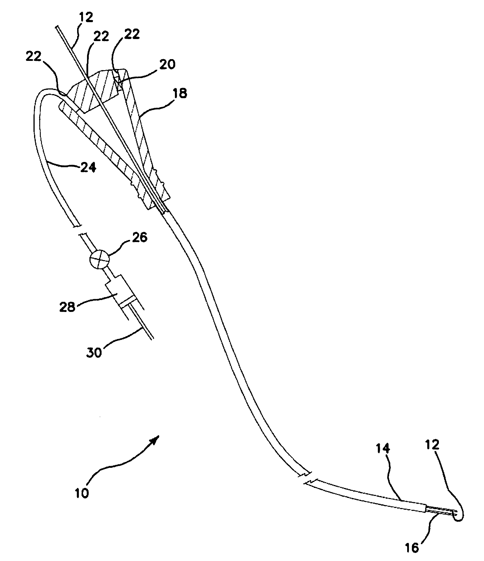
[0045]The balloon catheter 10 of the illustrated embodiment is a single use medical device designed to provide temporary vascular occlusion or balloon catheter flotation while providing a port for distal contrast injection or guidewire placement. The catheter 10 may be used for procedures requiring angiography, wedge pressure measurements, or any other procedure where a vessel needs to be occluded while maintaining a distal lumen. The balloon catheter 10 in its deflated state passes through a small introducer, and in its inflated state increases to a size 8-10 times the diameter of the introducer ID.

[0046]The balloon catheter 10 that can fit through or be telescopically disposed in an introducer (not shown), such as a cardiac sinus introducer. The balloon catheter 10 as shown in partial longitudinal cross-sectional view in FIG. 1 is comprised of a telescoping inner catheter 12 and outer catheter 14 with a folded or wrapped balloon 16 that is attached to the inner catheter 12 and out...


PUM


Abstract

A balloon catheter, for use with an introducer, includes an outer catheter, a telescopically disposed resilient inner catheter and a high-aspect, distal, inflatable balloon having one end of the balloon coupled to the inner catheter and an opposing end of the balloon coupled to the outer catheter. The balloon is joined at its corresponding ends to the corresponding inner and outer catheters, so that the balloon, when inflated, buckles and twists the inner catheter inside the outer catheter. This creates forces which automatically return the balloon to the wrapped configuration when deflated. The balloon diameter to length aspect ratio is equal to or greater than 1. The balloon is wrapped around the self adjusting inner catheter extended from the outer catheter when the balloon is deflated so that the outer and inner catheters with the deflated balloon fit and are disposable through the introducer.

Description

BACKGROUND OF THE INVENTION[0001]1. Field of the Invention[0002]The invention relates to the field of cardiac balloon catheters and the methods of manufacture of the same.[0003]2. Description of the Prior Art[0004]Cardiac balloon catheters are well known in the art, having been introduced by Swan and Ganz in the 1970's as balloon flotation catheters. Versions of these catheters are currently used for temporary vascular occlusion; ie Swan-Ganz and Pulmonary Angiography catheters by Edwards Lifesciences (Irvine, Calif.) and Corodyn Right Heart Catheters by B. Braun (Bethlehem, Pa.). These catheters are dual lumen catheters with a distal compliant balloon bonded to the distal end in fluid communication with one of the lumens, with the other lumen being used for injection of radiopaque dye for performing angiography of the pulmonary arteries. The limitations of these catheters when being used for coronary sinus venography in a patient with heart failure is that the balloon is inherently...

Claims


Application Information

Patent Timeline
Patent Type & Authority Applications(United States)
IPC IPC(8): A61M25/10A61M25/095A61F2/958
CPCA61M25/1006A61M25/1034A61M2025/1093A61M2025/0175A61M2025/1004A61M25/1038
Inventor KURTH, PAUL A.ARMOUR, ANDREW W.
Owner PRESSURE PROD MEDICAL SUPPLIES INC
Why Eureka
Try Eureka