Systems and methods for analysis and treatment of a body lumen

a technology of lumen and analysis method, which is applied in the field of system and method for analysis and treatment of the lumen, can solve the problems of stenosis of the lumen, reduction in the efficacy of the stent, and few, if any, highly safe and commercially viable applications, and achieves the effects of facilitating analysis of the lumen wall and angioplasty balloon characteristics, reducing the time or cost of the procedure, and little to no additional risk to the patien

Inactive Publication Date: 2010-11-11
CORNOVA
View PDF100 Cites 13 Cited by
  • Summary
  • Abstract
  • Description
  • Claims
  • Application Information

AI Technical Summary

Benefits of technology

[0015]Embodiments of the present inventive concepts are directed to systems and methods that provide physicians performing lumen-expansion procedures with useful information about the lumen wall without any significant increase in their procedure time or cost, and with little to no additional risk to th...

Problems solved by technology

A risk with a conventional stent, however, is the reduction in efficacy of the stent due to the growth of the tissues surrounding the stent which can again result in the stenosis of the lumen, often referred to as restenosis.
However, there are very few, if any, highly safe and commercially viable applications making use of this spectroscopic data for combining diagnosis and treatment in a PTA or PTCA procedure.
In addition, dynamic and optimal control over the expansion of the balloon during angioplasty procedures is very limited, including during pre-dilation of the vasculature prior to stent delivery, dilation during stent delivery, and post-dilation after delivery of a stent.
For example, under-expansion of an angioplasty balloon may require deployment of an additional catheter and stent in order to complete the desired treatment and/or to ensure that an under-expanded stent is not blocking blood flow through a vessel, which can complicate procedures, resulting in increased risks, and added expense.
However, this technology has a limited resolution of about 300 micrometers.
As a result, many angioplasty and stenting procedures over-expand the lumen, which can result in unnecessary trauma and damage to the lumen wall, complicating post-deployment recovery, and increasing the likelihood of re-closure of the lumen (restenosis).
Angioscope technology is also generally used ...

Method used


Image

  • Systems and methods for analysis and treatment of a body lumen
  • Systems and methods for analysis and treatment of a body lumen
  • Systems and methods for analysis and treatment of a body lumen

Examples


Embodiment Construction

[0098]The accompanying drawings are described below, in which example embodiments in accordance with the present inventive concepts are shown. Specific structural and functional details disclosed herein are merely representative. The inventive concepts described herein may be embodied in many alternate forms and should not be construed as limited to example embodiments set forth herein. Accordingly, specific embodiments are shown by way of example in the drawings. It should be understood, however, that there is no intent to limit the present inventive concepts to the particular forms disclosed herein, but on the contrary, the present inventive concepts are to cover all modifications, equivalents, and alternatives falling within the spirit and scope of the claims. Like numbers refer to like elements throughout the description of the figures.

[0099]It will be understood that, although the terms first, second, etc. may be used herein to describe various elements, these elements should n...


PUM


Abstract

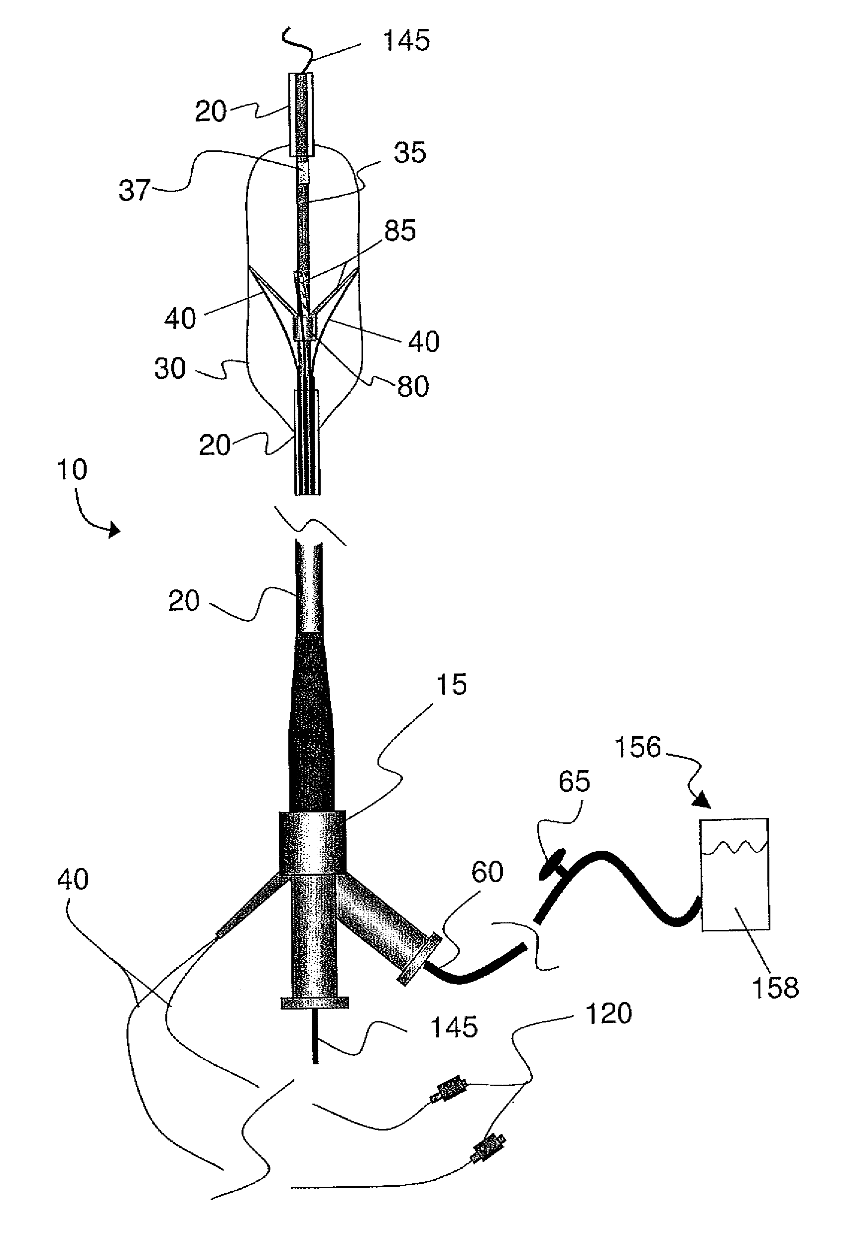
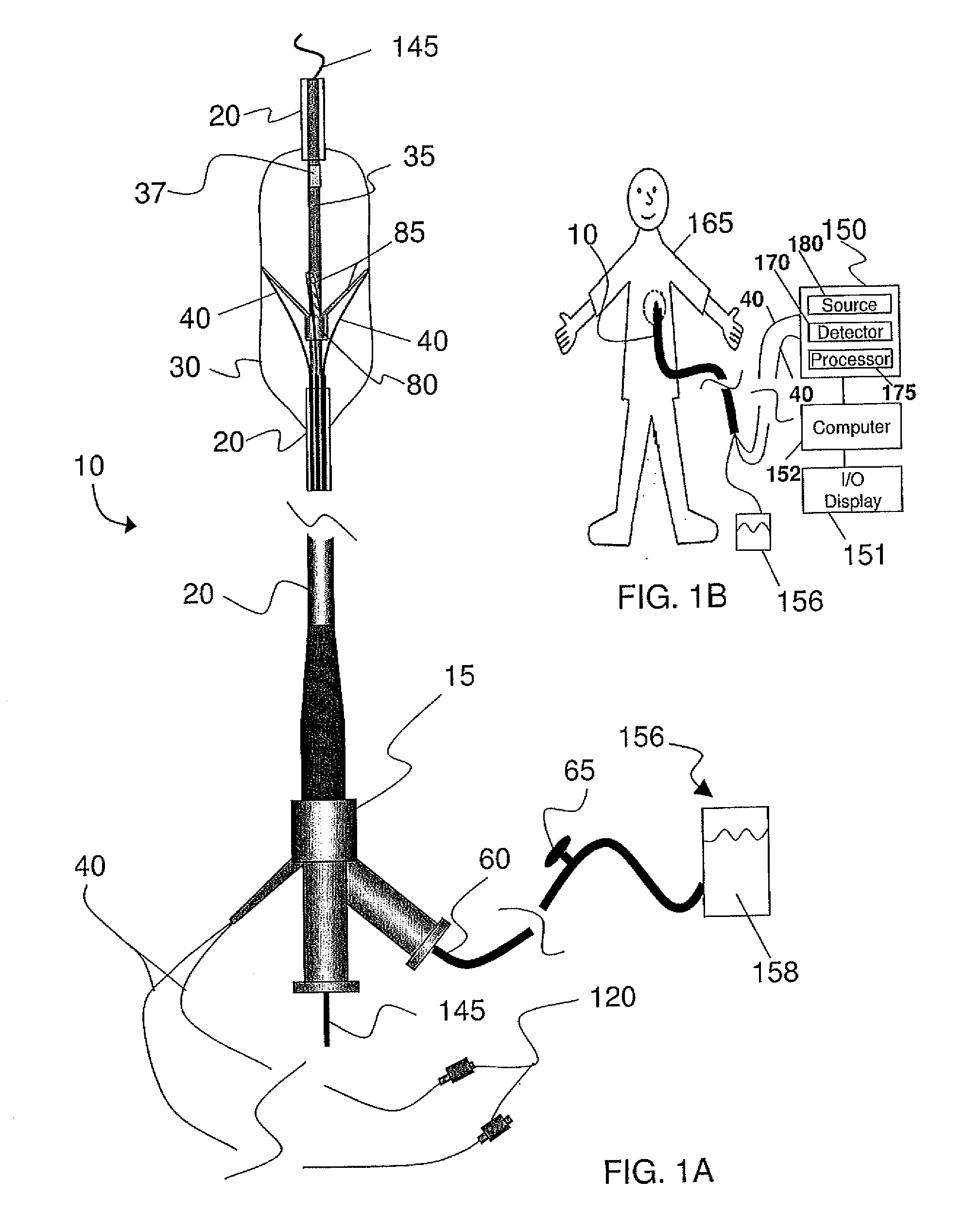
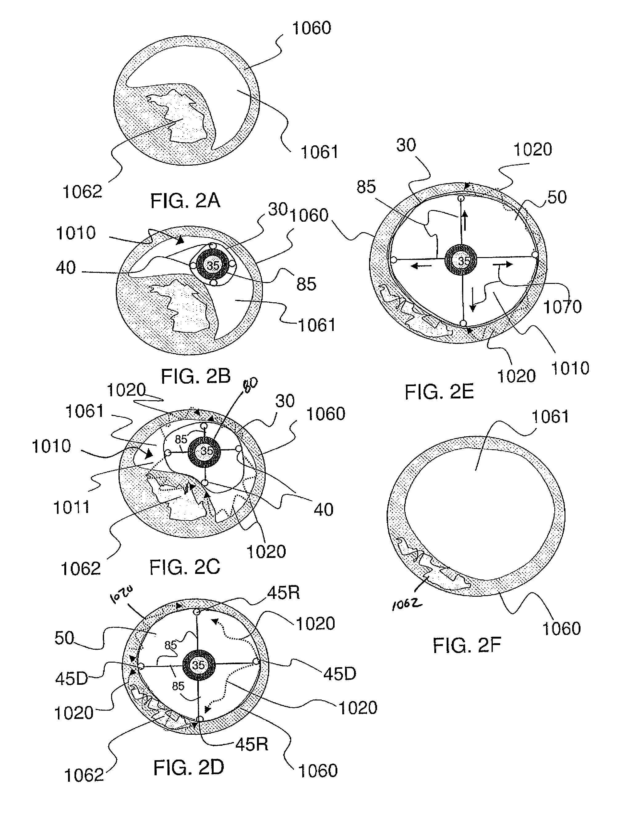
A system for analyzing a body lumen including a flexible conduit that is elongated along a longitudinal axis, the flexible conduit having a proximal end and a distal end; at least one delivery waveguide and at least one collection waveguide extending along the flexible conduit, a transmission output of the at least one delivery waveguide and a transmission input of the at least one collection waveguide located along a distal portion of the conduit; a spectrometer connected to the at least one delivery waveguide and the at least one collection waveguide, the spectrometer configured to perform diffuse reflectance spectroscopy, wherein the spectrometer emits at least one primary radiation signal of a wavelength having an absorption coefficient of between about 8 cm−1 and about 10 cm−1 when transmitted through a highly aqueous media; a controller system configured to calculate at least one of an extent, area, and volume of highly aqueous media based on the amount of absorption of the at least one primary radiation signal measured through the highly aqueous media by the spectrometer.

Description

RELATED APPLICATIONS[0001]This application is a continuation-in-part of U.S. patent application Ser. No. 11 / 537,258, filed Sep. 29, 2006, which claims the benefit of U.S. Provisional Application No. 60 / 824,915, filed Sep. 8, 2006, U.S. Provisional Application No. 60 / 823,812, filed Aug. 29, 2006, U.S. Provisional Application No. 60 / 821,623, filed Aug. 7, 2006, U.S. Provisional Application No. 60 / 761,649, filed Jan. 24, 2006, and U.S. Provisional Application No. 60 / 722,753, filed Sep. 30, 2005, the entire contents of each being herein incorporated by reference in their entirety. This application further claims the benefit of U.S. Provisional Application No. 61 / 180,068, filed May 20, 2009 and U.S. Provisional Application No. 61 / 310,337, filed Mar. 4, 2010, the entire contents of each being herein incorporated by reference in their entirety. This application is related to U.S. patent application Ser. No. 11 / 834,096, filed on Aug. 6, 2007, published as U.S. Patent Application Publication...

Claims


Application Information

Patent Timeline
IPC IPC(8): A61B6/00A61F2/958
CPCA61B5/0066A61B5/0075A61B5/0084A61B5/0086A61B5/0071A61B5/6852A61B5/6853A61B2017/22001A61N5/0601A61B5/02007
Inventor RYAN, S. ERICTANG, JINGGAMBALE, RICHARD
Owner CORNOVA
Why Eureka
Try Eureka