Separation membrane for solid polymer fuel cell and separation membrane-catalyst electrode assembly

a fuel cell and membrane technology, applied in the direction of cell components, electrochemical generators, electrolytes, etc., can solve the problems of difficult to reduce the electrical resistance of the resin membrane, high cost of perfluorocarbonsulfonic acid resin membrane, and limit in cost reduction, etc., to achieve high hydroxide ion conductivity, high mechanical strength, and high non-permeability to fuel

Inactive Publication Date: 2010-11-18
TOKUYAMA CORP
View PDF3 Cites 16 Cited by
  • Summary
  • Abstract
  • Description
  • Claims
  • Application Information

AI Technical Summary

Benefits of technology

[0039]The membrane of the present invention is a membrane for polymer electrolyte fuel cell, which has high hydroxide ion conductivity, yet has high non-permeability to fuel, particularly to liquid fuel, stability in water or liquid fuel, and high mechanical strength. Moreover, the membrane of the present invention is superior in bondability to catalyst electrode layer. As a result, the present membrane has high hydroxide ion conductivity at the interface with catalyst electrode layer and can maintain such high hydroxide ion conductivity over a long period.
[0040]The polymer electrolyte fuel cell using the membrane of the present invention can give a high cell output for long time owing to the above-mentioned excellent properties of membrane.

Problems solved by technology

However, the following problems are pointed out for the cation-exchange fuel cell using the perfluorocarbonsulfonic acid resin membrane.
(ii) The perfluorocarbonsulfonic acid resin membrane is expensive and there is a limit in cost reduction.
(iii) Since the physical strength of the resin membrane is low, it is difficult to reduce the electrical resistance of the resin membrane by making thin the resin membrane.
However, the above problem (i) has not been solved by using any of such hydrocarbon cation-exchange membranes.
For these reasons, the adhesivity between the catalyst electrode layers 4 and 5 and the anion-exchange resin membrane is inferior and the adhesion at their interface tends to be poor.
As a result, the adhesion strength at their interface tends to decrease.
Therefore, poor adhesion tends to appear at the interface and peeling occurs ultimately between the anion-exchange membrane and the catalyst electrode layer.
Their bondability, however, is not sufficient.

Method used


Image

  • Separation membrane for solid polymer fuel cell and separation membrane-catalyst electrode assembly
  • Separation membrane for solid polymer fuel cell and separation membrane-catalyst electrode assembly
  • Separation membrane for solid polymer fuel cell and separation membrane-catalyst electrode assembly

Examples


first embodiment

of Membrane

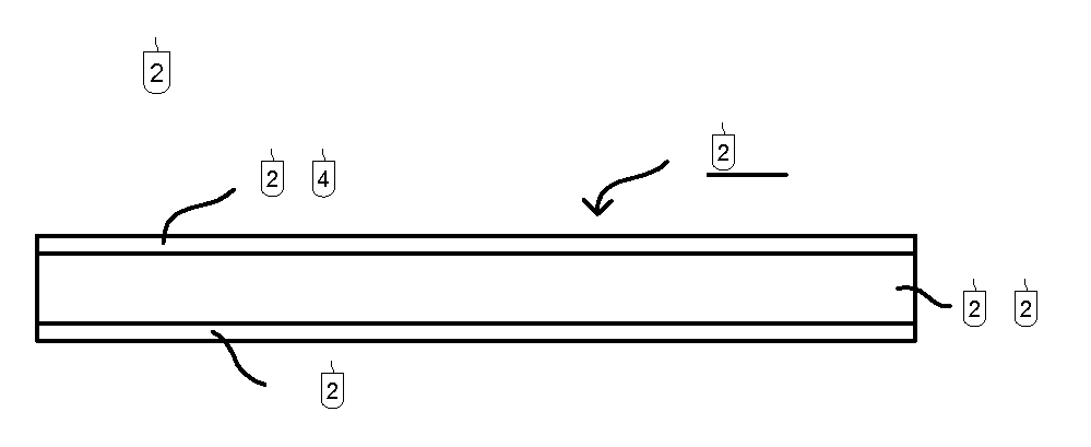
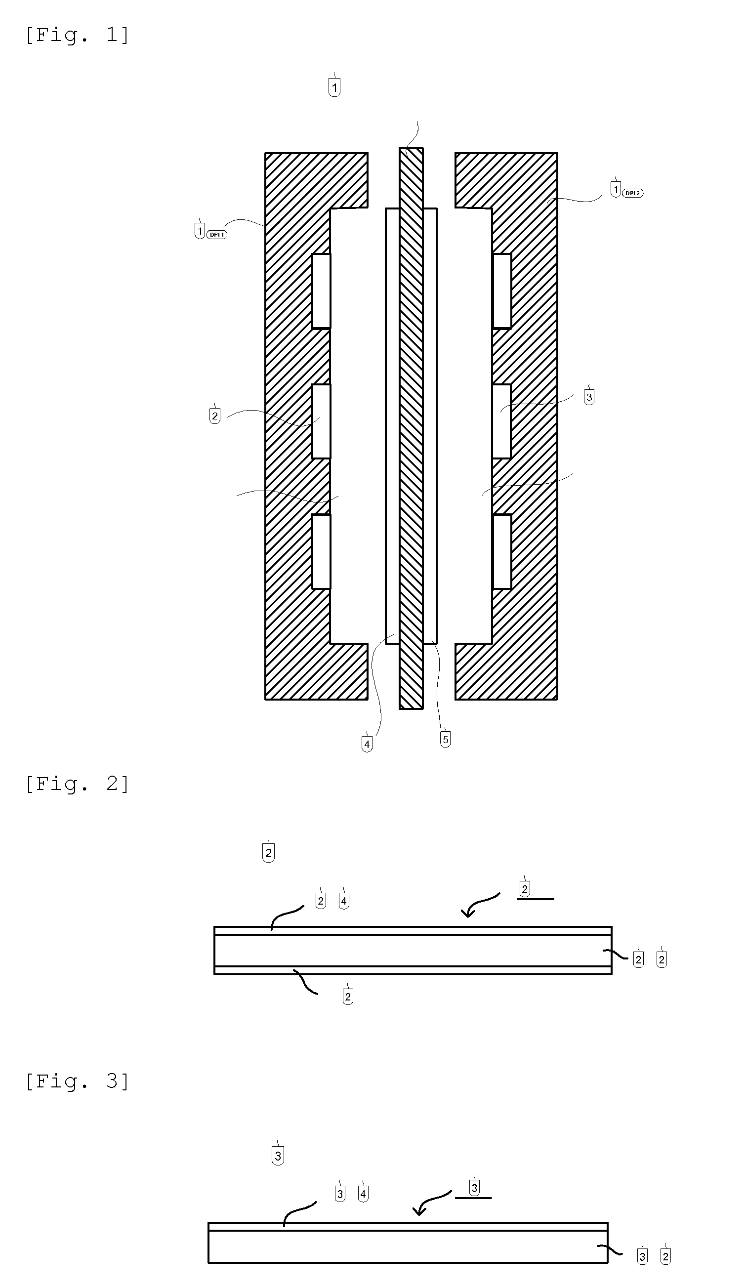
[0047]In FIG. 2 is shown a constitution of the membrane for polymer electrolyte fuel cell, of the first embodiment of the present invention (hereinafter, this membrane may be referred to simply as membrane for cell). In FIG. 2, 200 is a membrane for polymer electrolyte fuel cell, wherein adhesive layers 204 and 206 are formed on both sides of a hydrocarbon anion-exchange resin membrane 202.

[0048]In FIG. 3 is shown other constitution of the membrane for polymer electrolyte fuel cell, of the present invention. In FIG. 3, 300 is a membrane for fuel cell, wherein an adhesive layer 304 is formed only on one side of a hydrocarbon anion-exchange resin membrane 302.

Hydrocarbon Anion-Exchange Resin Membrane

[0049]As the hydrocarbon anion-exchange resin membranes 202 and 302, any known hydrocarbon anion-exchange resin membrane can be used with no restriction. As the anion-exchange group, there can be mentioned, for example, primary to tertiary amino groups, quaternary ammonium salt ...

second embodiment

of Membrane

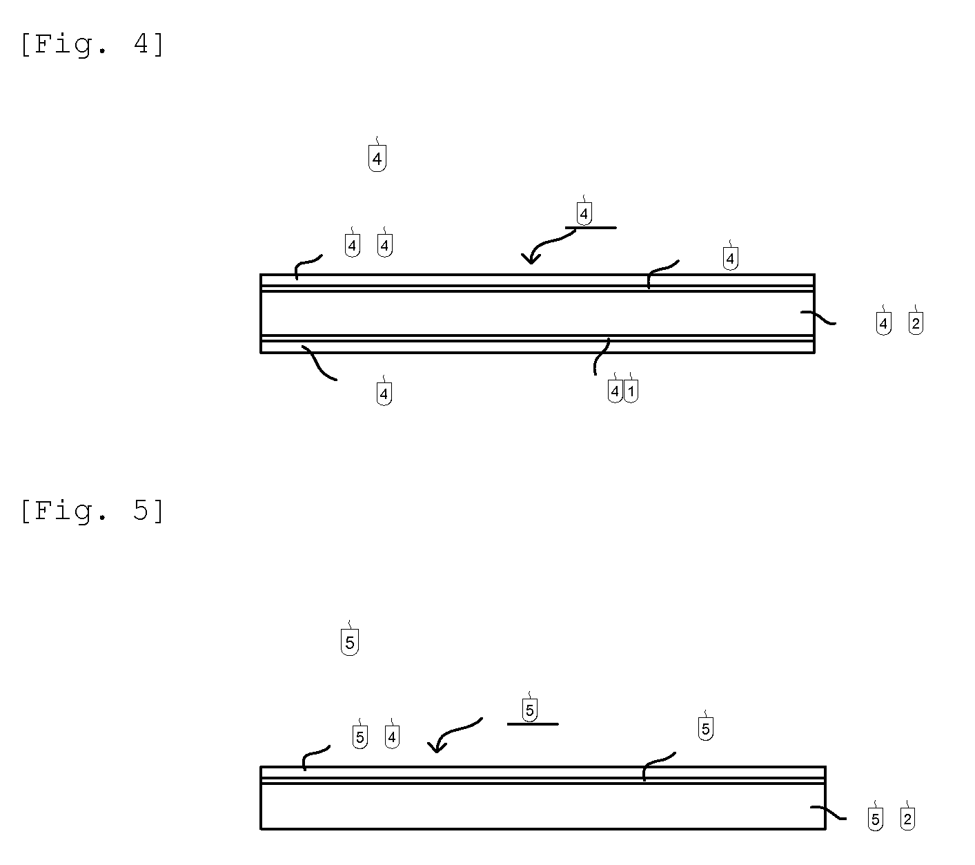
[0126]In FIG. 4 is shown an example of constitution of the second embodiment of the membrane for polymer electrolyte fuel cell, of the present invention.

[0127]In FIG. 4, 400 is a membrane for polymer electrolyte fuel cell, wherein intermediate layers 408 and 410 are formed on both sides of a hydrocarbon anion-exchange resin membrane 402 and adhesive layers 404 and 406 are formed on the surfaces of intermediate layers 408 and 410. That is, the intermediate layers 408 and 410 are formed between the hydrocarbon anion-exchange resin membrane 402 and the adhesive layers 404 and 406.

[0128]FIG. 5 shows other constitution of the second embodiment of the membrane for polymer electrolyte fuel cell, of the present invention. In FIG. 5, 500 is a membrane, in which an adhesive layer 504 is formed only at one side of a hydrocarbon anion-exchange resin membrane 502 and an intermediate layer 508 is formed between the anion-exchange resin membrane 502 and the adhesive layer 504.

[0129]In t...

production example 1

[0218]There was prepared a monomers composition consisting of 100 mass parts of chloromethylstyrene, 3 mass parts (3.5 mol % of the total polymerizable monomers) of divinylbenzene, mass parts of a polyethylene glycol diepoxide (molecular weight: 400) and 5 mass parts of tert-butyl peroxyethylhexanoate. In this monomers composition was immersed, at 25° C. for 10 minutes under atmospheric pressure, a porous membrane (thickness: 25 μm, porosity: 37%, average pore diameter: 0.03 μm) made of a polyethylene (PE, weight-average molecular weight: 250,000) to infiltrate the monomers composition into the porous membrane.

[0219]Successively, the porous membrane was taken out from the monomers composition and covered, at the both sides, with a polyester film (a peeling material) of 100 μm in thickness. Then, the covered porous membrane was heated at a nitrogen pressure of 0.3 MPa at 80° C. for 5 hours to polymerize the infiltrated monomers composition.

[0220]The membrane-shaped material obtained ...


PUM

PropertyMeasurementUnit
Young's modulusaaaaaaaaaa
pore diameteraaaaaaaaaa

Abstract

Disclosed is a membrane for polymer electrolyte fuel cells, which is composed of a hydrocarbon anion-ex-change resin membrane wherein an anion-exchange group is covalently bonded to a hydrocarbon resin, and an adhesive layer formed on at least one side of the hydrocarbon anion-exchange resin membrane. The membrane for polymer electrolyte fuel cells is characterized in that the adhesive layer is made of an anion-exchange resin having a Young's modulus of 1-1000 MPa.

Description

TECHNICAL FIELD[0001]The present invention relates to a membrane for polymer electrolyte fuel cell and a membrane-catalyst electrode assembly produced using the membrane. More particularly, the present invention relates to a membrane for polymer electrolyte fuel cell, made of an anion-exchange resin membrane, a membrane-catalyst electrode assembly, and a fuel cell in which the membrane and the assembly are incorporated.[0002]The membrane comprises an anion-exchange resin membrane and an adhesive layer formed thereon, made of an anion-exchange resin having a Young's modulus of 1 to 1,000 MPa at 25° C. Or, the present invention comprises the anion-exchange resin membrane, the adhesive layer, and an intermediate layer formed between them.[0003]The membrane bonds well to a catalyst electrode layer via the adhesive layer. As a result, the interfacial resistance between the membrane and the catalyst electrode layer is small and output of the fuel cell produced using the membrane is high.B...

Claims


Application Information

Patent Timeline
Patent Type & Authority Applications(United States)
IPC IPC(8): H01M8/10
CPCC08J5/2243H01M8/1023H01M8/1053C08J2325/04H01M2300/0082H01M2300/0094Y02E60/521H01M8/1058Y02E60/50
Inventor SADASUE, KAZUYUKIFUKUTA, KENJIWATAHIKI, YUKIYANAGI, HIROYUKI
Owner TOKUYAMA CORP
Why Eureka
Try Eureka