
Method and apparatus for non-or minimally disruptive photomanipulation of an eye

Inactive Publication Date: 2010-11-18
LARSEN
View PDF13 Cites 46 Cited by
  • Summary
  • Abstract
  • Description
  • Claims
  • Application Information

AI Technical Summary

Benefits of technology

[0045]In an eleventh aspect, the invention provides a method and a system for simultaneous use of multiple treatment beams entering the eye, each forming its own separate focus or target volume where a desired light-elicited chemical reaction or structural alteration change takes place, while avoiding side-effects that would follow from having the total energy delivered to the eye concentrated in a single focus.

Problems solved by technology

Presbyopia is defined as a decrease in accommodative amplitude of the eye resulting in an inability to correctly focus light on the retina from objects at variable distance.
For many people surgery is not an option because of lack of access to modern standards of surgical treatment.
Even in industrialized countries the burden of treatment creates significant problems for the health care systems.
Molecular cross-links and other types of degradation disrupt the optical and mechanical properties of the lens.
However this method has several drawbacks.
Firstly, with the eye closed it is not possible to determine exactly where in the lens the eye is being treated, which in turn may result in damages as the same position may mistakenly be treated several times. Secondly, the correct dose of laser light applied to a position within the eyes to achieve a significant clinical result is highly individual and may vary with the position in the lens.
With set values of the laser this may result in ineffective under-treatment or damaging over-treatment.
Damages may occur due to local evaporation of the constituents in the lens resulting in gas blisters (cavitation bubbles).
On the other hand, when using methods such as described in U.S. Pat. No. 6,726,679 it is difficult to adjust the amount of energy, so as to obtain sufficient treatment effect while avoiding or minimizing undesired effects, such as gas blisters or photodamage of the cornea or the living layers of the lens.

Method used


Image

  • Method and apparatus for non-or minimally disruptive photomanipulation of an eye
  • Method and apparatus for non-or minimally disruptive photomanipulation of an eye
  • Method and apparatus for non-or minimally disruptive photomanipulation of an eye

Examples


examples

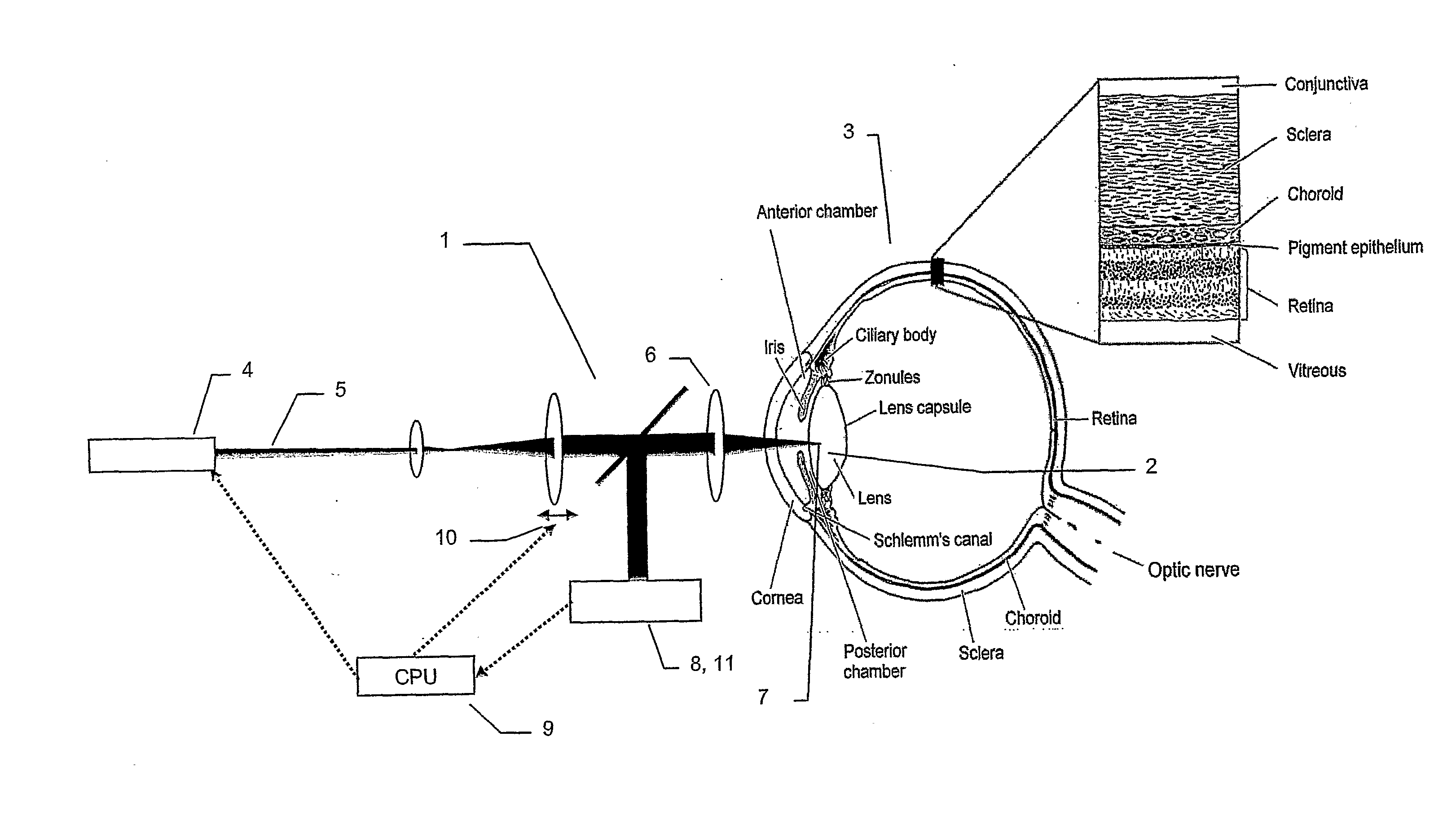
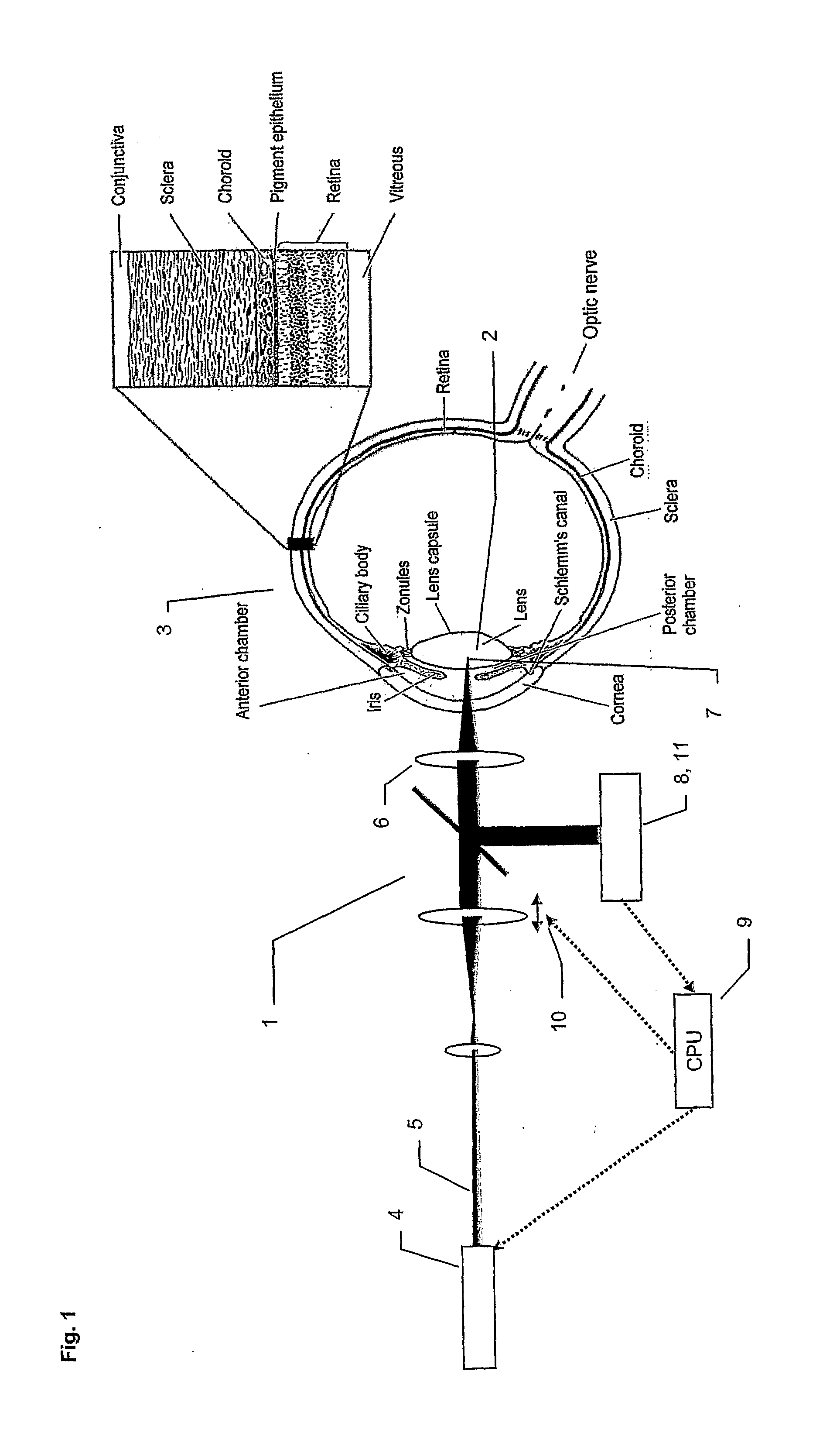
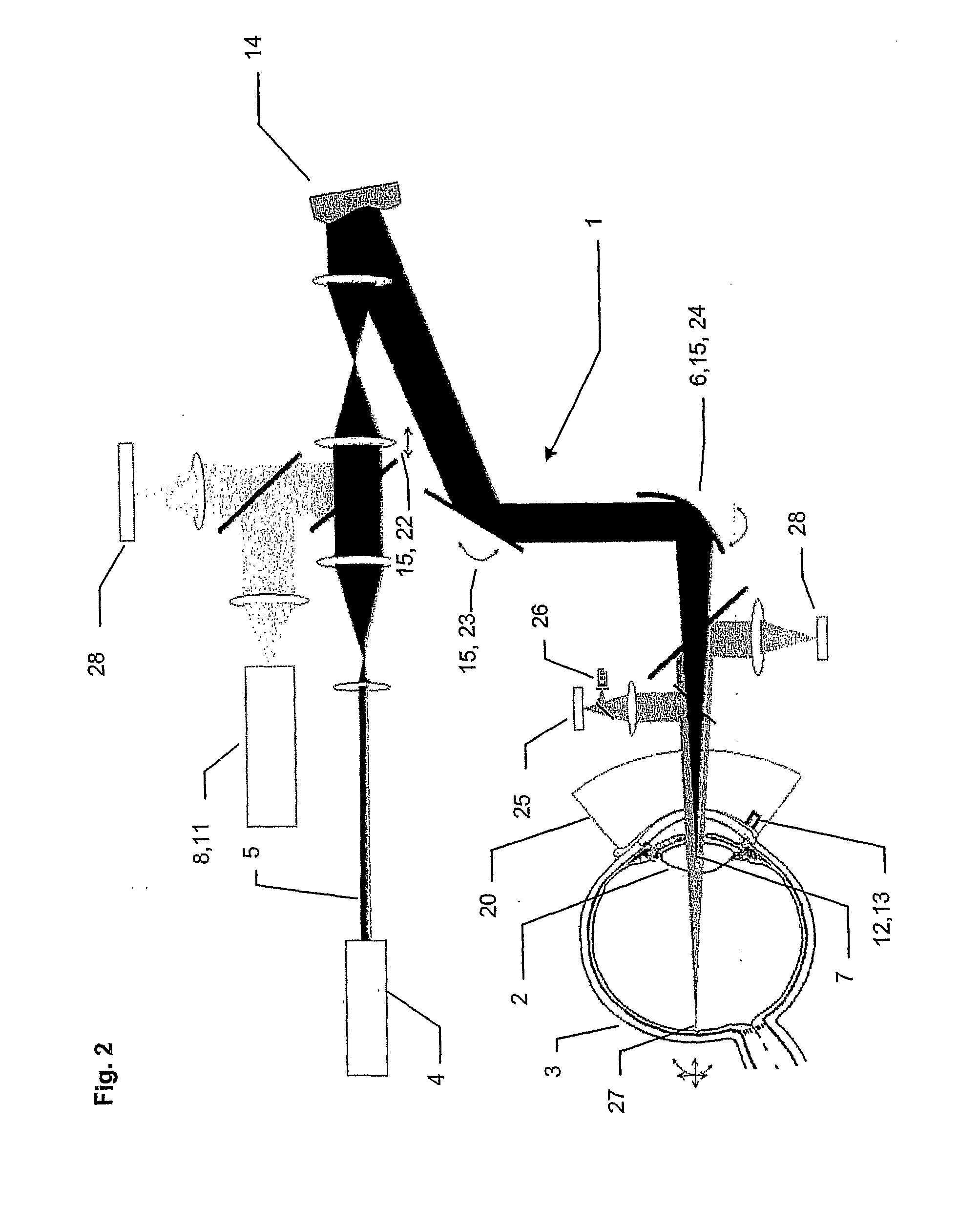
[0116]The following example provides further details of a system according to the invention such as shown in FIG. 1. The present example a system for lens phototherapy system uses one or more sources of light to aim and photomanipulate a selected volume of the lens of the human or animal eye. A specific embodiment of the invention uses an 800 nm titanium-sapphire laser at 275 kHz repetition rate, 238 femtossecond pulse duration, pulse energy 0.04 μJ, peak power 0.18 MW, and transverse target area radius of 10-200 μm. After acquiring a target area in the lens by the using of classical imaging optics, which may include slit-beam illumination and / or Scheimpflug real-time photography (not shown), a laser pulse or pulse train is applied in incremental energy steps to arouse a succession of events in the target volume, the nature of these events being detectable by the optical signature recorded by the spectrometer. These events include but are not limited to backscatter, fluorescence, Ra...


PUM


Abstract

The invention related to a method and a system for non- or minimally disruptive photomanipulation of the lens and / or its constituents collectively or selectively of an animal or human eye, comprising focusing a treatment laser beam into a selected part of the lens and / or its constituents collectively or selectively where treatment is intended to occur, pulsing of said treatment laser beam, scanning the beam over at least a part of the lens, measuring one or more types of radiation from the said selected part and utilizing this measurement to decide to stop the said treatment laser beam or to adjust at least one of the parameters: focus, intensity, wavelength, pulse length, repetition frequency, pulse train length, scan velocity, size of scanned volume, scan repetitions, and scan pattern of said treatment laser beam.

Description

[0001]All patent and non-patent references cited in the application, or in the present application, are also hereby incorporated by reference in their entirety.FIELD OF INVENTION[0002]The present invention relates to a method for non- or minimally disruptive photomanipulation of the lens and / or its constituents, collectively or selectively, of an animal or human eye.BACKGROUND OF INVENTION[0003]Opacities in the eye are primarily caused by cataract which is globally the leading cause of blindness, whereas hardening of the lens is primarily related to presbyopia.[0004]Presbyopia is defined as a decrease in accommodative amplitude of the eye resulting in an inability to correctly focus light on the retina from objects at variable distance. This is usually noticed by emmetropic subjects (persons who do not need spectacle or contact lens correction for distance vision) between age 40-50 as inability to see close objects clearly.[0005]When an human is born, the lens is transparent even to...

Claims


Application Information

Patent Timeline
IPC IPC(8): A61F9/008
CPCA61F9/008A61F9/00825A61F2009/00897A61F2009/0087A61F9/00838
Inventor LARSEN
Owner LARSEN
Features
  • Generate Ideas
  • Intellectual Property
  • Life Sciences
  • Materials
  • Tech Scout
  • Unparalleled Data Quality
  • Higher Quality Content
  • 60% Fewer Hallucinations
Learn More