Radiation-selective absorber coating and absorber tube with radiation-selective absorber coating

a radiation-selective absorber and absorber tube technology, applied in the direction of superimposed coating process, coating, light and heating apparatus, etc., can solve the problem of adverse effect on the overall layer system, and achieve the effect of high reflectivity

Active Publication Date: 2010-11-25
SCHOTT SOLAR AG (DE)
View PDF34 Cites 18 Cited by
  • Summary
  • Abstract
  • Description
  • Claims
  • Application Information

AI Technical Summary

Benefits of technology

[0036]These small layer thicknesses for the reflective layer that is reflective in the infrared range are possible because the materials gold, silver, platinum and copper have a very high reflectivity and, in a preferred embodiment, as a result of the packing of the reflective layer and the adhesion-enhancing layer between two barrier layers, cannot diffuse away into other layers or are not

Problems solved by technology

With a thickness greater than 50 nm, no improvement in adhesion promotion is detectable and, at the same time, as a result of higher t

Method used


Image

  • Radiation-selective absorber coating and absorber tube with radiation-selective absorber coating
  • Radiation-selective absorber coating and absorber tube with radiation-selective absorber coating
  • Radiation-selective absorber coating and absorber tube with radiation-selective absorber coating

Examples


Embodiment Construction

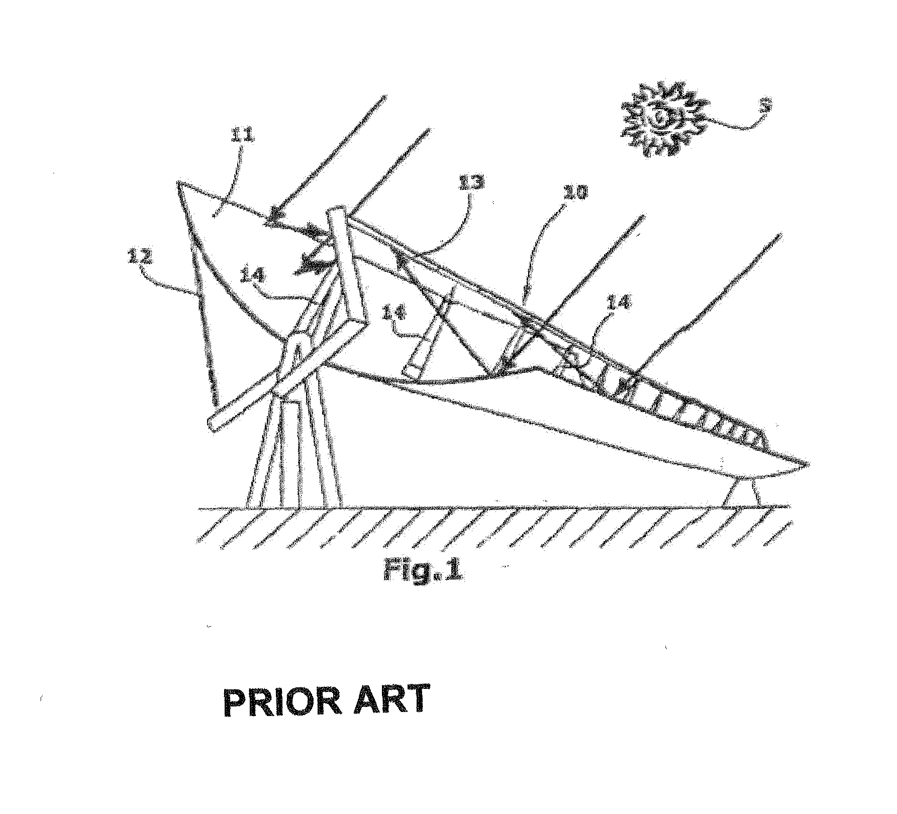
[0047]FIG. 1 illustrates a parabolic trough collector 10, which has an elongated parabolic reflector 11 with a parabolic profile. This parabolic trough collector 10 has a structure that is generally known in the art. The parabolic reflector 11 is held by a support structure 12. Along the focal line of the parabolic reflector 11 there extends an absorber tube 13, which is fixed to supports 14 connected to the parabolic trough collector. The parabolic reflector 11 forms a unit with the supports 14 and the absorber tube 13, which unit is pivoted about the axis of the absorber tube 13 and thereby tracked uniaxially to the position of the sun S. The parallel solar radiation incident from the sun S is focused by the parabolic reflector 11 onto the absorber tube 13. A heat carrier medium, in particular water, flows through the absorber tube 13, the latter being heated by the solar radiation absorbed. At the outlet end of the absorber tube, the heat transfer medium can be withdrawn and fed ...


PUM

PropertyMeasurementUnit
Temperatureaaaaaaaaaa
Thicknessaaaaaaaaaa
Thicknessaaaaaaaaaa

Abstract

The radiation-selective absorber coating, in particular for an absorber tube of a parabolic trough collector, includes a reflective layer which is reflective in the infrared range, at least one barrier layer arranged below the reflective layer, at least one absorption layer arranged above the reflective layer, an antireflection layer arranged above the absorption layer and at least one adhesion-enhancing layer arranged between the barrier layer and the reflective layer. The adhesion-enhancing layer preferably is a molybdenum layer, but can also be provided by a copper, titanium, titanium oxide, or silicon layer. The adhesion-enhancing layer preferably has a thickness of 5 to 50 nm.

Description

CROSS-REFERENCE[0001]The invention described and claimed herein below is also described in German Patent Application 10 2009 022 059.3, which was filed on May 20, 2009 in Germany. The aforesaid German Patent Application provides the basis for a claim of priority of invention for the invention claimed herein below under 35 U.S.C. 119 (a)-(d).BACKGROUND OF THE INVENTION[0002]1. The Field of the Invention[0003]The invention relates to a radiation-selective absorber coating, in particular for an absorber tube of a parabolic trough collector, which comprises a reflective layer that reflects in the infrared range, at least one barrier layer arranged below the reflective layer, at least one absorption layer arranged above the reflective layer and an antireflection layer arranged above the absorption layer. The invention also relates to an absorber tube that has the aforesaid radiation-selective coating, and to a method of operating a parabolic trough collector using this sort of absorber t...

Claims


Application Information

Patent Timeline
IPC IPC(8): F24J2/48F24J2/00F24S10/70F24S20/20F24S23/74
CPCF24J2/07F24J2/14F24J2/4652F24J2/485G02B1/11G02B5/08C23C28/36C23C28/322C23C28/34C23C28/341C23C28/345C23C28/3455Y02E10/41F24S23/74F24S70/30F24S20/20F24S70/225Y02E10/50Y02E10/40F24S70/20
Inventor KUCKELKORN, THOMASSILMY, KAMELDREYER, SEBASTIAN
Owner SCHOTT SOLAR AG (DE)
Why Eureka
Try Eureka